
| Dot Matrix Printers Printers > Dot Matrix | Navigation Icons Guide
|


Basic Mechanism - Characters Made From Picture Elements
Any shape can be made using a pattern of points or "pixels" - picture elements. The technique is very common; it is the basis of television and is used to display information on screens ranging from the little LCD displays on mobile phones up to the giant display boards used at pop-concerts and football grounds. Dot matrix printers use the same technique for printed pages. 
The term "dot matrix" is normally used for a particular kind of impact printers - printers that use mechanical pins to squeeze ink out of a ribbon and onto the paper. Inkjet and laser printers also use a matrix of dots, but individual pixels are smaller and less evident in the printed page.
Impact printing gives dot matrix printers an advantage over inkjets and laser printers in some circumstances. The dot matrix process is simple, mechanical and reliable in hostile environments. The ink is cheap - and when it runs out it does so gradually. Disadvantages are the relatively large, crude pixels which aren't appropriate for photographs and the costly electromechanical printhead used to produce them.
Printheads are normally designed to have enough print pins to make a line of text at one pass.  To display the upper-case alphabet a matrix of 5 x 7 is needed. On a matrix 7 x 9 it is possible to form upper and lower case characters quite readably. More pixels gives a more readable print. It is possible to represent any kind of graphical information using pixels. Dot-matrix printers first appeared in the early 1970's. The competition was then from
| 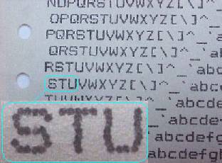 Dot Matrix Text from a Newbury Data 640 printhead. This is a sample sent with a printhead. The engineer hasn't got belt tension right, hence the line position drift - on the top line the letter N is well to the left of the letter O on the next line. |
| The dot-matrix mechanism uses a typewriter -like chassis and ribbon. The typewriter's fixed font printhead is replaced with pins to form an image out of pixels. It would be possible to use one pin but the carriage would have to make 9 passes to produce a line of print. A typical printer has 9 or more pins held vertically in a print-head that scans horizontally across the page picking out the shapes of alpha-numeric characters as it goes. This is called "serial dot matrix". |  |
An alternative mechanism lines the pins up across the page. This mechanism could be called a parallel dot matrix - but is more often called a "line printer" (risking confusion with band-printers) or "shuttle printer".
Market Position.  |  |
From 1970 to about 1990 dot matrix printers were the first choice for people wanting low volumes of printed output from a computer. Lack of alternative was the main reason.
Typewriters - conventional, golf -ball or daisy wheel - were all too slow. | Pen plotters were too expensive and too slow. | Bandprinters seemed inherently expensive. | Laser printers were too expensive to buy. | Thermal printers were too expensive to run. | Inkjets didn't appear until the mid 1980s and were unreliable at first. |
Dot matrix printers were the logical answer.
| The chassis - paper transport for vertical motion - carriage for horizontal motion - resembles a teletype or golfball typewriter. |
| The matrix mechanism uses a printhead with solenoid driven needles that can produce text and graphics. It's more flexible than a typewriter. |
| The dot matrix mechanism was well placed to take advantage of the microprocessor revolution of the 1970s - character generator ROMs and suchlike. A dot matrix printer based on two motors and a printhead and driven by a microprocessor could be made cheaply. |
| Costs per page are generally lower from a dot-matrix printer. The inked ribbon approach is hard to beat for putting ink where it is wanted on a page of text. High quality dot matrix printers can put ink on a page for about 0.1p to 0.3p per page. |
| Dot matrix is fairly slow in human terms. Most serial dot matrix printers produce one or two lines per second, so a densely printed page can easily take a minute. Lightly printed pages can be produced faster. Dot matrix technology does include "parallel" lineprinters - or "shuttles" - much faster but more expensive. |
| Graphics are poor - pixels are usually about 100th of an inch across and are quite visible and distinct - so neither text or pictures look great. |
| Users need a certain amount of knowledge and ability. Changing a ribbon in a recent dot-matrix is less difficult than changing the ribbon in an old spool-fed typewriter but typewriting was regarded as a skill. Users want the click in cartridge found on inkjets and matrix printers don't quite achieve that. |
In the 1980s laser printers became affordable for businesses and the new technology was adopted. Laser printers tended to replace daisy-wheel electric typewriters and dot-matrix printers from offices.
In the 1990s home PC buyers switched to inkjets. Colour doesn't add much to the purchase cost of an inkjet printer and instantly attracts people. The rather higher page cost of an inkjet isn't dramatic with the low volumes of material a home user typically produces.
Laser and inkjet technology have partly but not entirely displaced mechanical dot-matrix printers from the market.
| There is a perception that dot matrix is "old fashioned" which sometimes encourages people to use inkjets where they aren't appropriate. Actually all three technologies date back to about the same time. The first Centronics dot matrix printer and first Xerox experimental laser both date to 1970 and the continuous inkjet to the mid 1960s. Dot matrix isn't any older than alternative technology - it just doesn't do pictures very well. |  |
Dot matrix produces readable text on multipart listing paper cheaply and reliably. Dot matrix printers will work in environments where laser and inkjet printers would continually malfunction. However dot-matrix printers have more user - accessible parts and may be a bit more fiddly than other kinds of printer so they have fallen out of favour. Dot matrix still has a role in commercial work - delivery notes, invoices, Point of Sale terminals.
Dot matrix technology is particularly suited for ticketing and timeslip printing. The printer can be small and easily incorporated into something else. Thermal printers compete in this role, but dot matrix will tend to be more robust than thermal transfer, and cheaper to operate. Furthermore dot matrix printer designs can be made in small runs for a specific job.
Dot-matrix printers vary greatly in price and capability. The purchase price for a new machine can vary from below £100 to above £5000, and print-speeds range from 80 to 1000 or more characters per second. When dot matrix printers were mass-market they were low cost. As specialist devices they tend to cost much more. Specialist printers aren't cheap because they lack economies of scale in manufacturing and distribution.
Defining the market.
The dot matrix printer became commonplace in the 1980's, but is now confined to niche markets in businesses and organisations. Nevertheless its way of operating has defined the market.
- Inkjets owe a lot to dot matrix - the main difference is a change in printhead.
- Dot matrix designs established the instruction streams to produce graphics and control paper handling.
| Like the Teletype and band-printer, the dot-matrix printer expects to be fed a string of ASCII characters that will be placed on paper, line after line. Unlike its predecessors it can also print pixel graphics in any style the user wants. To develop the graphical capabilities of their printers manufacturers came up with all sorts of escape-codes and emulations, and these are still found built into later inkjet and laser printers. Inkjet and laser printers intended for use solely with Microsoft Windows are only just throwing off this heritage. | Escape Codes & Emulations |
| Dot-Matrix Mechanism - Outline |
| Dot-matrix printers form characters by mechanically punching a pattern of ink dots out of a ribbon and onto the paper. The dots are formed by pins, usually carried in a print-head. In principle the print-head could carry a single pin which would scan the paper and form the image. In practice it is normal to incorporate enough pins in the print-head to form a whole line of alphanumeric print at one pass. Dot matrix print-heads commonly have 7, 9, 18 or 24 pins. Printers have had as many as 48 pins. |  |
| The paper moves vertically across a platen, as it does in most printers. The platen in most dot-matrix printers is a rubber coated steel roller - a design dating back to the typewriter. The platen both helps feed the paper and absorbs energy from the printhead. The printhead sits on a carriage that scans horizontally back and forth across the page. The net effect produces raster scanning. |  |
| At the point where the print-head contacts paper the pins are usually arranged in a vertical column. The print-head scans horizontally across the page on the carriage, forming the line of characters as it goes. The smaller the pins the better the print quality. More numerous pins allow printing to be quicker and / or higher quality. |  |
| The pins in a dot-matrix printer are quite light, and can therefore move fast, at speeds between 1,000 and 3,000 cycles per second (1-3 kHz). This sort of speed is necessary, because characters formed on a dot-matrix machine will need about 9 times as many actions as those on a daisywheel or bandprinter. Printer designers have difficulty getting the speed of individual pins much beyond 2 kHz. Achieving high print speeds means providing more pins or faster movement, there is more on this below. |
|
Print Process.
The print process is as follows. The paper is positioned at a blank line on the paper. The input logic takes in a stream of characters and assembles the line to be printed in memory. When a line is available the print-head sets off from the left margin. As the head travels across the paper its position is tracked. For ten characters per inch the tracking might be in 1/100ths of an inch, but for closer character spacing it will be more accurate. Each print-head position corresponds to both a character to be printed and a column of dot-positions within that character. Columns of pixels are made by firing the pins in each position. 
The shapes of the characters are usually stored at manufacture in a ROM in the printer. (In recent printers the shape of the characters can also be downloaded into RAM). As the print-head is moved to successive locations, the character and column position required are looked up and drive circuits push the pins accordingly. A basic 9 pin print head might fire the top pin 9 times to produce the top bar on a "T", but scarcely ever fire the two bottom pins that produce the "tail" on letters like "q" or "g".
The high speed action required from the pins on a dot matrix printer demands quite a lot of electrical power - pin circuits may draw peak powers exceeding 100 watts - more than an amp of current at 80 volts. The total power is not that great because the duty cycle on each circuit will probably be under 5%. Printheads can get hot after a couple of minutes operation.
Looking up the dot pattern required for every character and dot position also requires a moderate amount of logic or processor power. Older printers tended to have some dedicated logic chips that match head position, character required and ROM lookup table. More recent printers generally do the job in microprocessor software - a dot matrix printer commonly has one processor for general control and another handling the print process.
Limitations.
The maximum speed of a dot-matrix printer is set by:
- the speed that the printhead pins can move – not much faster than 2-3 khz
- the number of pins in a head - typically 9, - 24 or 48 at a maximum
- the quality of print required - how many dots are required to form an image
A double-column head has an additional advantage because it can be made to function as a single head producing good quality, or to have the effect of two heads giving high speed but lower quality. Each column of pins fires at 2kHz, but the pair behaves as one column running at 4kHz. Some fast printers had two or more two-column heads.
| Electronics - Motors |
A substantial part of the innards of a printer is determined by the kind of motors it has.
A dot-matrix printer generally has two motors:
 About Paper Feed | The vertical or line-feed motor drives the paper through the print-station, usually by driving a cog-chain and forms tractors. This motor needs to be capable of starting and stopping quickly to allow the position of a print-line to be determined quickly- even loaded with several ounces of paper. |
 Carriage Action About Carriage Movement | The horizontal or carriage motor drives the print-head backwards and forwards within the print-station. This motor needs to be powerful because it has to accelerate and decelerate the print-head at either end of its travel. Print-heads are a collection of small but powerful solenoids, so they are almost inevitably quite heavy. |
In small printers the two motors are commonly both steppers. In large fast printers it is common to find the fast-moving carriage driven by a DC- Encoder motor - it's more complicated but packs a bigger punch.
There are two broad classes of motor used in printers - and indeed in most other machinery.
 DC Encoder Paper Feed Action | DC encoder motors. The encoder motor is a conventional DC motor like that used in toys and other small devices. This has a permanent magnet stator locked in position, often as part of the casing. The stator creates a strong magnetic field within the motor. The armature is the shaft assembly in the middle of the motor, which is usually a stack of iron plates wound with coils - there are typically 3, 5, or many coils. When one or more coils are fed with current the armature creates its own magnetic field and moves to align itself with that of the stator. The armature coils are fed by brushes through a commutator on the armature shaft, so as the armature moves the coils are switched on and off and as a result the motor continually turns. DC motors provide a powerful and responsive action in a relatively small package. DC motors do pose a problem - motor response isn't precisely predictable so a control circuit doesn't know where the mechanism has got to. DC motor designs typically rely on an "encoder" to give feedback on position in some way. The encoder is typically a slotted disk with an opto-sensor on the back of the motor. |
 Stepper Paper Feed Action | Stepper motors - a "brushless" motor, usually with a strongly magnetised armature in the centre and two or three coils mounted around the outside. Each coil is activated in turn and the magnetic attraction or repulsion forces the armature round. Stepper motors don't have the brush and commutator mechanism to give continual motion, instead they rely on some external electronics to provide the alternate operation of the coils. One advantage of a stepping motor is that it only moves when the control electronics says to do so. When there is no current the magnet tends to resist movement, a phenomenon called "detent". Within certain limits a microprocessor control circuit can control where the mechanism has got to very precisely by just feeding successive pulses to the coils. The control circuit can know what the mechanism is doing without feedback. |
There are fashions in motors. In the early 1970s stepper motors were rather too novel so printers used DC motors even at the cost of needing complicated optical feedback sensors and supporting logic. By the 1980s steppers were common and hybrid ICs to control them were making circuitry cheaper for manufacturers, so that most printers used stepper circuits. But then the cost of the support circuitry for optical encoders fell and new hybrid ICs to control DC motors came along. So recently the DC encoder has been back in fashion, not just in printers but in things like robot arms. The DC encoder with support circuitry can look complicated but controls power very accurately. Of course, there is nothing to stop designers using a stepper with an encoder.
| Paper Feed. Vertical Action -Form Feed & Linefeed | |
| Printing machinery usually has a line through it where printing takes place, sometimes described as the print station. A page passes through the print station a line at a time. Moving the paper through the printer is often described as "vertical feed" - it is often done against gravity to give the paper some tension and keep it flat. Most printers have historically been aimed at producing text - often with graphics as a bit of an afterthought. Paper motion tends to be a succession of linefeed - stop actions. In a serial dot-matrix printer (or an inkjet) the printhead on its carriage typically makes one line of text per pass of the printhead. The height of the area printed at one pass is sometimes called the "swath". Each swath is followed by a linefeed action.
|  |
| Paper Feed History. Paper handling has been a source of all sorts of innovation over the years. | |
In a conventional print works paper is typically fed into the print process
- continually from a roll and guillotined to shape later, sometimes called web feed
- as A0 sheets using vacuum pickups - the sheets are printed full-width then later folded and guillotined.
Tractor feed seems to have originated as a way to move paper at high speed. The first generation of computer printers were attached to mainframes which performed several million arithmetic operations per second. The operations performed by early mainframes were typically largely arithmetic aimed at payroll, stock control and accounting, so they may have been elaborate in human terms but didn't take the computer long. Data typically came from disk or tape and was destined to be printed - so fast printers were a priority. A 1200 line per minute printer was a bottleneck on a mainframe, so sometimes printing went back to another tape drive called a spooler - then the tapes were mounted on other drives that fed directly into printers. The word "spooler" is still used to describe a cache of material waiting to be printed.
Most high speed printers used tractor feed paper. The paper has sprocket-holes down the margins so the machinery can easily drive paper through the print path with no danger of it slipping. Tractor fed paper became an industry standard.
There is some of this heritage in recent computer printers. Computer printers are:
- aimed at lower costs - £500 rather than the £50,000 up for a professional press.
- need to be capable of working on a single small sheet.
Dot matrix printer paper feed mechanisms are usually a bit of a compromise. They use
- a typewriter style platen to grip the paper
- forms tractors with a continuous feed of pre-folded paper with serrated tear-offs.
| Platen roller mechanisms are often used to grip the paper. Most dot matrix printers can take cut sheet paper in the platen like a typewriter. This works with many printers but on older and simple machines the user has to stand by to feed pages which can be thoroughly inconvenient for anything longer than a couple of pages. Page alignment has a nasty tendency to drift because the rollers don't grip firmly enough. |  Printhead Faces Into Platen Dot Matrix Index Page |
Tractor Feed is the standard method to feed paper into dot matrix printers. The tractors are narrow belts or cogs with prominent conical teeth or sprockets spaced to fit sprocket-holes in the paper. There is usually a tractor at either side of the paper. Sprocket feed is used on photographic film and other devices where precise alignment is needed.
The paper is usually fan fold continuous form 14-7/8th wide with serrated tear-off lines at 66 line 11 inch intervals. This odd paper style seems to be a very old standard and probably dates back to the days of the tabulator (it was sometimes called IBM paper).
| Tractor feed usually grips the paper after the print-station because gravity keeps the paper taught as it is printed. The tractor pulls the paper through the print-station so its a pull-tractor. The problem with pull tractors is that when the print job ends an extra page has to be fed so that the user can tear off the printed fanfold sheets. The user could unload and reload the printer - but loading paper onto tractor feed sprockets is fiddly so that isn't practical. To get printing on demand for single pages and labels, printers can use a push tractor underneath the print station. A push tractor allows users to tear a page off immediately when it is printed without wasting a blank sheet. Push tractors are the best way to handle short print runs of one or two pages but because paper feed might be less reliable they aren't usually standard on low cost printers. |  Push Tractor Dot Matrix Index Page |
Cut sheet feeders can often be added to printers and are standard on some recent models. There are several types. One distinction we can make is between passive and active cut sheet feeding.
Passive cut-sheet feeders have a tray, some feed rollers and a cog chain to work the rollers. The cog chain engages with the main vertical feed motor cogs when the cut sheet feeder is mounted on the machine.
Paper feed action isn't completely straight forward. To insert a page the cut sheet feeder first needs to pick the page up - start one page and no other moving. Then these rollers or more usually another set of feed rollers have to propel the page forward at least until it is gripped by the platen rollers. If the page is gripped by the platen rollers then the feed rollers might disengage.
To work a couple of sets of rollers which engage then disengage without using any extra motors a passive cut sheet feeder normally has an interesting collection of shaped, spring-loaded and satellite gears. When it wants to pick up a page the printer might rotate its vertical feed backwards and a satellite gear engages the pick-up stage and pushes the paper to the start point. Then some forward rotation advances the paper into the printer. Printers move the feed motor back and forth as it engages different roller sets. Some passive cut sheet worked reasonably well but they were often disappointing - causing a lot of paper jams and misprints.
Cut sheet became a user expectation with laser printers so recent printers often have cut-sheet feeders built in. The paper feed dot matrix printers work best with is tractors pulling on sprocket holes. Best print quality is usually achieved by pulling the paper because this keeps it flat.
Active cut sheet feeder have their own motor(s) working the roller set, so they are more expensive. There is generally a need for some connection to the printer to get power and control signals so that the feeder knows when to do what. At one time a firm called Rutishauser made high quality sheet feeders.
Motor drive for the paper path is often a stepper motor with a strong detent. The stepper motor gives the short jerky actions of the paper path reasonably efficiently. Early printers often had just a few steps of the motor per line - which meant they could only space the page at sixth-inch intervals. Recent printers are usually more flexible. Some high speed printers have used DC encoder motors to achieve very high paper feed rates.
Sensors are usually limited to a paper-out switch. Most low-cost printers have very little feedback on what the paper path is doing. The printer just assumes that instructions to the motor are carried out and the page moves accordingly. There is usually a paper-out switch and the printer should halt when there is no paper because otherwise the printhead and / or the platen may be damaged. Designers have tried all sorts of elaborate tricks to monitor how the paper is behaving but the improvement in usability is often small.
Paper Feed Trays etc
A lot of dot matrix printers will feed paper in from the rear and out through the top, which can be convenient because it just takes space on a desk. It does tend to take quite a lot of space and it doesn't tend to be terrifically reliable.
Most printers come with at least one wire tray to be fitted to the top where paper exits. This often doesn't look terrifically functional but it often does have a purpose - to discharge static from the paper and allow it to fold more easily.
Dot matrix printers often have special stands, or benches with a hole jig-sawed into them, or even silent operation hoods. Some of these ideas are more functional than others.
| Horizontal Action - Carriage. | |
| Most printers print one line of text per pass. The print mechanism is usually carried back and forth across the page on a carriage. For historical and practical reasons one sweep across the page usually produces one line of text from a dot-matrix printer. Making one line of text and allowing lower-case in a Latin alphabet means at least 9 pins in the printhead and possibly two or three times as many. Printheads are therefore quite heavy. Bidirectional printing means the printhead acts both as it moves forward and backward - doubling efficiency. |  Carriage Scans Back & Forth Dot Matrix Index Page |
Carriage speed matters. The carriage needs to carry out its scanning action as rapidly as possible. The speed of pins in the head is the main limit on printer speed but the rate the carriage can travel is related. Obviously if the pin speed were doubled the carriage could travel twice as fast - doubling print speed. There is also some sort of balance between the number of pins packed into the head - which makes it heavy - and needing more power to drive it back and forth across the page. Continually accelerating a heavy printhead one way and then the other does not seem a particularly efficient process and does require a fairly powerful motor. Other than the printhead pins the carriage motor is usually the most stressed part of a printer system - and the most likely to give trouble.
Carriage rails normally provide support. The carriage normally grips one large rail, with a nearby smaller rail providing a bit of support. It may seem curious but carriage bearings rarely use rollers or ball bearings - these were tried on older designs but the need for a bit of elasticity in these bearings may have been a disadvantage. Almost all recent designs use either a brass / bronze or PTFE plastic sleeve on a steel rail. The carriage should slide very smoothly and easily. This is usually difficult to test because of course the carriage is usually connected to a drive belt and a motor - and they do not move particularly easily.
Carriage belts are toothed elastic material usually with a fibre or metal reinforcement. The belt loops across the width of the print-station with an idle wheel and tensioner at one side and the motor at the other. The motor has a toothed cog that meshes with the teeth in the belt. The carriage itself is locked to the belt at one point so, when the motor moves, the carriage is pulled in the appropriate direction. The most usual design is to have a motor at the right hand side, under the control panel. Older belts seem to be rubber and fabric, newer designs use fibre strings in an elastic compound usually orange in colour. Various different means of driving the carriage back and forth have been tried. The belt drive is one of those things that doesn't look particularly brilliant but works well in practice.
Carriage belt tension needs to be right. If the belt tension is lose the user will see "margin drift" where typically successive lines of characters don't all start in quite the same place. Bidirectional print shows the problem particularly strongly, successive print lines start in different positions. A printer with margin drift will print recognisable text but will be useless for graphics and bar codes.
The belt tension mechanism is usually a screw adjustment on the idle pulley at the left side of the printer.
Stepper Motors provide carriage drive on low cost printers. The microprocessor tells the motor to step forward or back and so far as possible it does so. A stepper motor typically has two coils and to move the motor the electronics alternately switches the current in the coils one direction then the other in a sequence. The drive circuitry is two circuits called bridges - four power transistors which switch on and off connecting the coils so that current flows in the correct direction.
Providing the processors demands stay within the carriage subsystems capabilities then what the software is asking is reflected in the the state of the hardware. The print control processor often has only one way to discover where the carriage is - there is usually a sensor on the left side of the chassis and when it operates the carriage must be there. This explains why printers can apparently go barmy - wrecking the paper and losing the margin. The processor instructing the motors hasn't a clue what has happened and only when the user presses a switch will the action stop.
DC-encoders are used for carriage drive in some high speed printers. The DC motor is a fairly familiar object used in toys, tape recorders and electric drills. The DC motor does not behave in a very predictable manner but it can pack a lot of power into a small space. Combined with an optical encoder the DC encoder is a good match for the carriage drive task.
- the power to give rapid acceleration to a half kilo or so of printhead
- combined with the encoder feeding back information about the result to the printer
The DC motor only needs one bridge which makes the output simpler than the stepper. However the encoder feeds back information usually via an interrupt. Handling a stream of interrupts either needs:
- a powerful processor that can run the instructions quickly
- a separate circuit or processor that can deal with the encoder task.
- very careful programming so that interrupts from the encoder mesh with whatever else is going on.
DC encoders have tended to be used in more expensive printers that could afford several processors or support circuitry.
| Printhead. | |
| Printheads typically produce one line of text per pass over the page. Minimally understandable Latin text in upper case can be built from 7 x 5 pixels. Lower case text needs 9 x 5 pixels. Giving a better shape to characters implies a 14 x 7 or 14 x 9 matrix. Basically the more cells there are in the character matrix the better the characters will look. Dot matrix printers have upward and downward limits on pixel size. The upward limit is set by the sixth -inch 4.167mm spacing of typical text. |  |
| The text itself needs some margin at top and bottom so it probably needs to be about 3.5 mm high. The area printed in one pass is sometimes called the "swath". With a 3.5mm swath each of the 9 pins can be little more than 0.3mm thick. This corresponds with ordinary experience - people choose pens with 0.2 to 0.4 mm tips to write with. |  |
| The picture shows the dimensions of an Epson 9 pin head. (The pins are round, but the enlargement makes them look a bit square). 0.25mm pins give 100 dpi print. There is no unbreachable downward limit on pin size but there is one set by experience and practicality. A 24 pin Epson head has a 3.4mm swath and 01.8mm pins in two rows. Engineers have found the finer pins more vulnerable to damage. Some printers were made with "letter quality" 48 pin heads. These actually had two or more rows of pins in the head. Below 0.1 mm the metal of the pins was too insubstantial and vulnerable to bending. Most 48 pin heads proved rather too vulnerable - they were notoriously failure prone. | 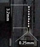 Epson 9 Pin Head
|
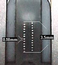
| The human eye still picks up individual dots if they are 0.1 mm across - ie 250 dpi. Print from a 24 pin head is pretty good but it isn't going to rival 600 dpi or 1200 dpi laser printing, never mind 5,000 dpi inkjets. Dot-matrix technology no longer really aims at the quality print market so printhead designs in recent printers often have fewer pins - 18 pins is a good compromise for a head aiming to be robust. This picture shows an 18 pin Newbury Data head. In this case the two rows of 9 pins are used alternately to give faster print. | 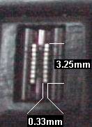 |
| Dot matrix pixel shape is normally circular. Circular pins are the shape with least mechanical resistance to rapid movement and the best wear characteristic as well as being easiest to manufacture. Circular pixels are not ideal because the page cover isn't very good. Printers often have a "near letter quality" print mode that joins the dots by overprinting. NLQ print is slower but generally does look much better than draft mode. The practical limit on dot-matrix technology is the speed of the pins. A full width computer form is about 13.5 inches wide. Printed at:
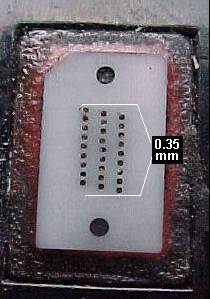
|  Epson 24 Pin Head |
Having several columns of pins means the printhead is starting the outline of one character whilst it is still filling in dots in the last but, although this looks complicated in human terms, the control logic easily deals with the problem.
Better use of energy. The flight of a steel needle driven by an electromagnetic field is a complex of electrical circuits and mechanical resonances. Drive circuitry on high speed printers usually has something like 40 volt positive and negative rails and connects a coil with a DC resistance of about 4 - 8 ohms momentarily. Superficially this means a massive current around 10 amps but with pins firing at about 2 kHz and a substantially shorter duty cycle the head impedance is much higher - drive transistors are typically rated at about 1- 2 Amps.
Thermal control. Most recent thermistors have a heat sensor in the core of the head where the temperature should be greatest. The printer slows things down when the temperature rises.
Forced-air cooling has potential. Put a fan in the carriage to blow cool air through the coils. Only a few printer designs tried this because paper dust tends to clog the fan. Epson printheads are particularly noted for carrying big finned aluminium heatsinks.
| Multi-Headed Printers. | |
Mechanical problems make it difficult to put more than two or three columns of pins into one print-head, there's just nowhere to pack the solenoids. This needn’t limit printer speed.
| Putting two print-heads into a machine is a fairly common way to increase printer throughput. One deals with the left hand of the print, the other with the right. Newbury Data 680 printers have two heads each with two columns. If the printer is producing something like an invoice with a bit more print on the left than the right this nearly doubles the speed. |  |
Running two heads at once just requires a bit more processor capability to handle double the load of character formation lookups - but that isn't a problem for any recent microprocessor. The ND680 uses a 10MHz Motorola 68000.
Printers with up to four heads have been built. C.Itoh and Facit were particularly noted for this kind of design, which had high throughput. Large numbers of heads make the carriage heavy, however, so the horizontal motor needs to be more powerful to handle the weight. Obviously a printer with several heads is changing its nature.
| Shuttle Printers. |
| Rather than arrange a row of printheads it is also possible to arrange the pins across the page to simultaneously print a row of dots. Since each character will be ten or more dots across, a 132 character page will be 1320 dots across. Arranging 1320 dot positions would need rather too many pins to be provided on a practical printer. Each mechanism would need to be 100th of an inch thick or stacked in some way. The resulting printer would be phenomenally fast. |  |
One solution is to arrange a page-width of pins on a moveable cradle. The number of pins is cut tenfold to a manageable 132 or less (66 ?). The cradle is driven rapidly backwards and forwards. Each pin then serves one or two character positions. The more pins there are the faster the print speed and the less violent the shuttle action.
The result is a device called a shuttle printer. The term "line printer" is also used - but perhaps better applies to bandprinters. The shuttle printer can also be called a parallel dot matrix.
Shuttle printers can produce ordinary characters and graphics with equal ease. The mechanism can be equipped with different numbers of pins - a 132 pin machine can achieve band-printer like speeds of 600 lines per minute or more. Double the pins and double the speed. Shuttle technology is well developed, so the machines can deliver a low price per page.
Unfortunately shuttle printers are mechanically quite complex, so they are expensive.
There is also an obvious problem - springing backwards and forwards on a 1/10th inch travel is not a natural motion for a large piece of metal holding 132 solenoid and pin assemblies. If the printer is to achieve 600 lines per minute and the character matrix is 9 dots high with 3 dots separation between lines then the machine must do 600 X 12 oscillations per minute - 120 per second.
Shuttle mechanisms vary. Honeywell Bull made a printer with the shuttle on metal-leaf springs and a voice coil drive. Printronix seem to have favoured a motor with an axle. To pick up the actual position of the shuttle most use an opto-encoder.
With good engineering using rubber shock absorbers and heavy metal supports designers have managed to confine the noise of the shuttle mechanism and pins to a relatively inoffensive hum when the printer lid is closed.
| Graphics. about graphics support |
Dot matrix printers have a huge advantage over bandprinters - they can produce graphics. Normally the dot matrix receives a character, then looks up in its ROM the pattern of pixels to make the pattern on paper. In graphics mode instead of a pattern being looked up for every print position, the print-head is told exactly when to print dots in a manner corresponding with the picture.
Graphic printing is not quite as simple as it sounds. The printer memory needs to store all the dot positions required by the print-pins before the head sets off from the margin. The printer needs some kind of instruction to tell it that the following data is not to be interpreted as characters but treated as pixels.
Memory used to be an expensive asset. Some old printers have small memories, so they shuffle the head across the page an eighth of a line at a time. Another problem is that the pins are arranged to deal with text at 6 lines per inch, with gaps between the lines. The platen may have to move and the print-head go back to fill in gaps. Some dot matrix printers perform abysmally when dealing with Windows output; inefficiency in the control process is the reason. The Epson MX100 (a very old machine) is very slow printing graphics. The Epson LQ1170 can give quite an impressive Windows printing performance at inkjet –like speeds. However even the best dot-matrix printers (things like the OKI 393 and Brother M4318 aren't really very good at graphics.
Because dot matrix designers didn't really think their machines would be used for graphics they economised on memory. Because there wasn't enough memory the printers didn't deliver the graphics performance the physical hardware could have achieved.
Pixel size is a real limiting factor in dot-matrix graphics. Dot matrix pixels in turn depend on the size of the pins. Reducing the pin size down close to 0.1mm seems to cause a reduction in printhead reliability. In future, improvements in materials might allow very small pins.
Instruction set limits are related to memory. Although the dot-matrix printer can produce graphics this capability wasn't immediately a big selling point in the 1970s because the computers of the time couldn't do much graphical. An image 250 pixels square with each pixel being 1 byte is 62,500 bytes - nearly a full memory for most 1980s microcomputers. When graphics did emerge as an interest the market became confusing. Far from the printer makers seeing graphical instruction sets as something they could unite on and standardise, they all saw it as something they could use to seize market advantage. However the moment a standard was in place it was overtaken. Having developed the "EscP" code to tell the MX80 and MX100 how to handle graphics, it took Epson a while to come up with "Esc-P2". Likewise Hewlett Packard went through several iterations of PCL - which originated as a dot-matrix instruction set.
Very few people today are likely to use a dot matrix printer if they have the least interest in graphics - a thermal printer would be a better choice in a factory, and an inkjet or laser in an office. However the dot-matrix mechanism still influences today's graphics instruction sets.
Bar-codes can be made quite acceptably providing the "picture" is kept large and the ribbon fresh. Barcode scanners are looking for contrast rather than a very neat pattern. Obviously if you reduce the image so that the thin lines are only made from one row of dots then there is a chance of the reader missing them altogether. A few dot matrix printers have escape code sequences to support barcode printing without any additional software.
Bar code reliability is usually very important - a business process breaks down if the bar codes can't be read properly and someone has to type a 13 digit number. A dot matrix will have difficulties with barcodes if:
- the ribbon isn't fresh enough to give adequate contrast
- the carriage belt tension is wrong - there will be some carriage drift.
- thermal printers - with a similar resolution but a more reliable mechanism - and capable of producing one label.
- laser printer - higher resolution allowing smaller and more reliable barcode labels.
| Colour |
Colour printing is relatively easy to achieve with a dot-matrix design. The usual approach is a ribbon-lift mechanism. Ribbon lifts were frequently seen on typewriters sold for accountancy, they had a red and a black stripe. The ribbon on a colour dot matrix has stripes in several different colours – cyan, magenta, yellow and black for instance. If the printer needs to mix bands to achieve the colour the head makes successive passes with the ribbon lift positioned.
A dot-matrix printer can never achieve much with colour because it cannot control the proportion of ink delivered to the paper - there either is or is not a dot of colour. Overprinting magenta with yellow gives red and so forth- but this just gives an 8-colour gamut. Dither patterns can mix the colours but they aren't very successful with a 0.25mm pixel size at 100dpi - or even with 0.1mm pixels at 250 dpi.
Dot matrix colour can be very useful - boxes and text look alright. Photo-realistic pictures are out of the question - although the result does have an interesting "pointilist" look. Individual pixels are too large, the positioning of the head on successive passes is too inaccurate and the mixing of inks placed on paper a second apart is too poor for good colour rendering. However if all that is wanted is to print "due now" in red on a statement then the extra cost of colour printing may be justified.
Colour isn't used all that much on dot matrix printers. That may be because most designs create problems. For instance, the ribbon lift succeeds in throwing the ribbon off the printhead altogether. Ribbon life is usually much shorter because the colour bands are narrow.
There must be few reasons to have colour dot-matrix these days, an inkjet or laser would almost always be a better choice. The main reason to have dot-matrix printers is to have low cost printout with a carbon-copy - which can't be in colour.
| Control Panels. |
Dot matrix printers started off with a few simple controls.
| Set TOF - Set top of form, the printer knows the head is at the top left of a page and so it will print the number of lines it has been told is the pagelength before automatically inserting a new page break. It is usually important that the printer does not print on the break in fanfold paper; not only is the text hard to read but pins may stick through the page, get trapped and bent. |
| Line Feed or Newline - Literally move the paper one line up. There is often a platen knob that winds the paper up but the button may be easier to use. To load and position the paper correctly put it onto the tractors, then press newline until the page-break is just beyond the printhead, then press TOF to tell the machine its at the Top Of Form. On a lot of printers holding Line-Feed in whilst turning the power on causes a self-test utility to run and print "ASCII Swirl". |
| Form Feed - Put exactly one blank sheet of paper out of the printer (at whatever formlength the printer is set to). |
| Online / Offline - When it's offline the printer isn't receiving commands from the computer. This won't necessarily stop it printing straight away because it may have a buffer full of information. Nor can you necessarily cancel what is in the buffer from the computer's print spooler, because the data has already been sent. It may take a reset to stop an unwanted print. |
There are usually one or two purely manual controls as well:
|
| Printhead / Platen gap is the space for the paper. Since paper thickness varies, so does the exact placing of the printhead. A few printers have an electronic motorised mechanism for this but there is usually a simple lever. Pulling the platen gap lever all the way back usually opens the paper tension plate as well - not every printer has one. |
| Paper path is often a lever as well, operating some internal cogs or clutches. |
On old printers there are often some other switches, perhaps behind a fold-down flap. Switches typically select interface type (RS232 or Centronics), Font, Character Pitch in CPI, NLQ, Line Pitch in LPI etc. The general idea was that only informed users would change these settings.
By the mid 1980s things started to get complicated. Printers could have all sorts of options so the manufacturers built in a menu (perhaps selected by holding TOF at power on), the printer then steps through asking the user which options to set.
At their peak, 5 to 10, years ago dot-matrix printers developed control panels worthy of Starship Enterprise. All the little levers that position paper grips and control platen gap were automated and controlled from the front panel.
This was done, of course, in an attempt to make things simple for users. This style of printer has all kinds of elaborate sensors and controls. Some printers have no user controls inside, everything is done with little motors controlled from an LCD front panel. For users these printers may be wonderful - although experience suggests they are mainly confused. For engineers these printers are a nightmare to work with, the sensors get dirty and malfunction and the printer sets the wrong platen gap, or throws out paper it is supposed to be loading. Trying to understand the front-panel controls on an unfamiliar printer requires patience - or the manual. Talking users through a problem is impossible - they are desperate for the single-button simplicity of an inkjet.
Most dot matrix printers have a Microsoft Windows driver. Very few dot matrix printers have a sophisticated Windows pop-up help to tell the users what to do. By the time Windows came along the users were hankering after inkjets and laser printers so that they could embed pictures and photographs in their documents. Dot matrix development became a backwater.
| Limits To Dot Matrix Development |
Impact printer designs have reached a point where few real improvements seem possible. The underlying technology is quite settled, the main possibilities are advances in materials and changes in the way the mechanism is presented.
The problem with impact printers using pins, bands or daisy-wheels is that they rely on non-repeating oscillatory motion at a scale of about 0.5 to 2 millimetres.
The power delivered at one end of the oscillation must be sufficient to drive ink off a ribbon into the paper. It must be possible to start and stop motion after one cycle because only about 1 pixel-space in 20 is actually printed.
Fabric Ribbon
Dot-matrix and shuttle printers transfer ink onto paper by impacting on a ribbon. Impact on a fabric ribbon was the mechanism used by the original typewriters, it is widely understood and cheap, but it does not seem capable of producing images that look good to the human eye. Not only is the pixel printed large - of the order 0.1mm but the fabric of the ribbon is pressured unevenly so the resulting pixel might be an ink-blot rather than a circle.
Carbon-coated film ribbon instead of fabric ribbon improves the print producing a more cleanly defined pixel. The problem with carbon-coated ribbons seems to be that they are quite expensive to make (or at least to buy). Multistrike carbon ribbons worked quite well.
Miniature Pins
In principle it might be possible for the pins and ribbon of a dot-matrix printer to be miniaturised add-infinitum to produce any dot-pitch. Machines aimed at high quality print tend to have 24 pins arranged in a column 1/10th of an inch high, giving a vertical resolution of about 240 dots per inch. By making the pins rather smaller and offsetting them some dot matrix machines claim a resolution of 360 dots per inch. 48 pin printers have been tried, but the miniaturisation of the coils, pins and jewels in the print-head seems to have been too extreme and some designs have been unreliable. It is also difficult to repeatedly position the print-head to within 1/300th of an inch. In practice, impact dot-matrix machines produce rather poorly defined line art pictures. Photographic quality just wasn't achievable.
It also seems difficult to reduce the tip of the print element below 1/10th millimetre – around 250 dots per inch. A smaller metal print element tip wears rapidly in contact with the paper and can be prone to accidental damage. Unless these limits are overcome using new materials - like carbon fibre or ceramic tips perhaps - impact printers cannot give fine-grained images.
A pin can only be fired or not. It is possible to get a darker mark by overprinting, or by offsetting the print position a bit and filling in spaces between the circular pixels. It is not possible to produce shades of grey and a dot-matrix machine can only make a crude attempt at printing photographs.
Fast Pins
It does not seem possible to get the frequency of oscillation above 3,000 per second without consuming a lot of power. (Power consumption tends to rise as the square of pin velocity).
New materials could give new life to the old designs – what seems to be needed is a pinpoint-thin object capable of moving much faster than 3,000 times per second with a "throw" rather more than a millimetre. Piezoelectric ceramics and electro-mechanical polymers might help transcend today’s limits.
In the absence of such a design advance manufacturers have turned to other print techniques - laser printers and inkjets.
Matching the Job
Some of today's dot matrix printers are not ideal for their job. In the low cost market there are several printers that were designed to give high-quality print for small office and home use. A user will generally be advised to buy an inkjet printer for this sort of work.
The ideal dot-matrix printer today is something simple and highly maintainable, well adapted to robust commercial work.
- The dot-matrix printer's main roles requires crude but readable print at reasonable speed.
- A 9 or 18 needle printhead is preferable to 24 or 48 needle - if the users want high quality they should look at another print technology. The printhead also needs to be reasonably big and robust. Plastic jewels, colour ribbon lifts and little cooling fans are likely to cause trouble and should be avoided.
- Print heads should either have a very long rated life, be cheap, or be repairable at low cost.
- The carriage motor needs to be able to accelerate the head rapidly - and preferably to print when the head is not up to speed. This can be achieved with belt-driven carriages using either stepper or DC encoder motor technology. In general, DC encoders are best.
- The printer should probably have self evident manual controls for paper loading and platen-gap adjustment - fancy electronic controls will go wrong.
- Graphical capability and fonts are probably unimportant. If graphics are needed an inkjet, laser or thermal printer is a better choice. Dot-matrix printers can cope with making the dots of alphanumeric characters but they aren't very good at double-height italics - fancy printing slows them down. A well adjusted dot-matrix printer can produce a bar-code - but its advisable to check very carefully that the readers can cope because a slight misadjustment in the printer will give hundreds of useless labels.
| Dot Matrix Mechanisms |
The mass market for dot matrix printing has gone, but there is still a clear role for the idea in things like point of sale terminals and ticket printers. Larger POS makers tend to have their own proprietary dot-matrix mechanisms.
There is a market for OEM mechanisms that can be incorporated into a range of designs.
| Environment |
Dot matrix printers are capable of being a very environmentally responsible technology. The only essential consumables are the pins in the printhead and the ribbon. The technology is more or less settled - it delivers about 250 dpi and doesn't have much capability for improvement so it would be feasible to build a printer where the mechanism was intended to have a life of 15 years or more - as indeed the old MT440 / 490 were designed to do.
In practice the way the market has moved is to put ribbons in a disposable plastic cartridge, and to make printheads so complicated and from such proprietary parts that they are only repairable at rather high costs. Rather than suffer a £200 printhead repair or a replacement at £600 (for larger models) a lot of users will buy another printer. On some older printers it was possible to buy field replaceable printhead needles.
Piezoelectric inkjets are potentially better because the only consumable is liquid or solid ink and the head doesn't even have to touch the paper. The advantage dot matrix heads have is that although they do wear out they have a long life and suitable designs can quite easily be repaired.
© Graham Huskinson 2010