
| Dot Matrix Printers - Carriage Printers > Dot Matrix > Carriage | Navigation Icons Guide
|

Carriage motors scan the printhead horizontally across the page. A printer with a line-width of print mechanism - a line printer or a laser mechanism - doesn't need a carriage motor. Serial dot matrix, inkjet and serial thermal printers all have a carriage and they all use similar mechanisms which date back to the age of teletypes and golf-ball typewriters.
The printhead normally sits on a carriage which runs along a couple of rails parallel to the paper surface. The carriage rails might ideally be very smooth so the carriage would just slide gracefully along it. A lot of carriage rails are like this.
Printers very rarely use two identical rails. Two rails need to allow a bit of play in the bearings, otherwise small amounts of dirt and misalignment cause the carriage to jam. The actual print mechanism has to stay an exact spacing from the paper, so play in the bearings in not permissible.
Usually there is one large rail (10 to 15 mm in diameter) that is highly polished and determines the carriage position rigidly. There is another guide rail with a lose fitting bearing that keeps the printhead pointing in the right direction.
Changing the position of the guide rail is one way to change the printhead gap.
The bearing on the main rail is usually a brass or PTFE plastic sleeve exactly the right diameter to slide on the rail. Some earlier printer designs used ball-bearing races or rollers but again these probably allowed to much play in position.
Lubrication of rails can be an issue. Many rails are meant to be kept clean rather than noticeably lubricated. The issue is that a printer is not usually a very clean environment. Paper is often quite dusty - the cutting machinery in the paper factory makes dust and swarf. The printhead pins knock bits of fabric off the ribbon. Some of this falls onto the carriage rail. If the ail is damp with oil then the dust sticks and gets carried into the bearing where it is likely to build up irregularly and cause wear and drag.
In general carriage rails should be cleaned rather than oiled. Users with an understanding of engines often dose the carriage rails with lots of oil, which may help temporarily but then turns into black gunge. The ight thing to do is usually to clean all the old oil off rails until they are shiny and remain so when the carriage is slid back and forth. Spray isopropyl onto the rails to get material out of the carriage bearings and clean it off with a tissue (idealy lint free but they are expensive). When everything is very clean give the rails a couple of dots of light oil.
Some printers have a fiber lubricant pad under the carriage - not exactly a convenient place for changing or cleaning it - but the printer will be out of warranty before it needs changing. The idea is that it provides a very thin film of oil.
Other designs just seem to rely on a one-off oiling with about five small drops of oil after a clean.
A really good clean of the mechanism usually means dismantling the printer. Removing the rails and getting inside the carriage bearings can be very difficult. With the drive belt disconnected the carriage should slide very smoothly. Normally its rather difficult to guage the carriage bearing condition because sliding it by hand has to overcome the tension in the carriage belt and turns the motor into a generator and it puts up some resistance.
Carriage width is typically either 9 or 14 inches, corresponding to paper widths around A4 or A3. the 14 inch "full size" computer printout paper also needs a 14 inch width.
Printer sizes tend to be in inches for the US market so 9 inches is 225 mm and 14 inches is 350mm. There are very few printers with a carriage width beyond 14 inches. Potentially there could be some uses for something wider in plotter tasks - but dot-matrix never caught on in this role.
It costs very little more to give a printer a wider carriage - although there are issues about how the ribbon will behave. With a really wide span it may make more sense to mount the ribbon on the carriage assembly rather than on the chassis.
The problem for the carriage motor is the mass of the printhead - typically a few hundred grams of metal and plastic. Ideally the printhead moves back and forth across the page. A further refinement of the ideal is movement at constant speed so that:
- the circuitry looking up the dot-patterns and firing the printhead coils can work at a constant speed.
- the positioning and impact on the paper is always the same.
The carriage motor typically gets about 1 inch of run up to accelerate to print speed - and it should turn the head round as soon as it's beyond the ptintable area of the paper. Accelerating a half kilo of head, carriage, belt and motor armature to speed, letting it travel 350mm in under a second and then reversing the action needs a fairly chunky motor and drive cicuit. Chunky is not a very scientific term and it should be possible to calculate exactly how much energy is needed to move 500gm head through 350mm and stop in one second. It doesn't necessarily help to be terribly accurate because line lengths vary, there is some resistance from the drive mechanism and the deceleration should be more a matter of regenerating power in the motor coils.
If the carriage drive uses an encoder motor then it doesn't need constant speed. The encoder can run a position counter that knows where the printhead is and fires the printhead pins accordingly. A few old designs of printers would fire the printhead pins in the correct positions even if you connected the carriage motor and pushed the carriage by hand.
The carriage drive mechanism is a compromise. Most printers use a toothed ubber belt to drive the carriage. Very often the carriage motor shaft ends in a relatively small toothed pulley which directly drives this belt. The pulley has to push against the elasticity of the belt and the two do make some resistance. The motor needs to be chunky because is not just accelerating the carriage it is dealing with resistance of the belt.
Carriage drive belts are usually under tension, typically applied by a screw adjusting the position of the supporting pulley at one side of the printer. The belt material is usually a fabric or even several woven steel wires embedded in an elastic material. The wire or fabric einforcement eliminates elasticity horizontally, but there is some in the teeth and this reduces wear and noise. Belt drives are surprisingly robust, but sometimes a serious carriage jam will rip teeth away.
Belt tension is adjustable - normally by a screw pushing the idle pulley away from the chassis. If the belt tension is too light the carriage position will be slightly indeterminate giving malformation of characters. The most likely sign will be margin- drift. When the printer is doing bidiretional print there will be a clear alternation in the starting position of successive lines. Margin drift may pass unnoticed on ordinary text but be very disruptive when the printer is used for columns of figures. Margin drift will completely wreck barcode printing. Margin drift can be largely eliminated by not using bidirectional printing, at the cost that the machine works at half speed.
Overtightening the belt can also cause carriage motion problems because the motor is being pulled so hard its bearings jam. There is also a danger in overtightening that the motor will strip the belt teeth.
Having the motor drive a cog-chain and a larger toothed pulley might be less likely to wear and more efficient. Some printers have used geared drive. A potential disadvantage is that slack in the gear chain would lead to slight uncertainty as to where the head was. Slack in the carriage positioning would mean print dots could be misplaced.

![]()

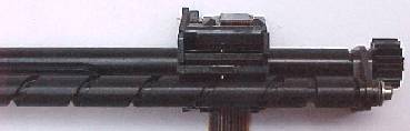
Drive wires are one alternative to the rubberised belt. The wires are usually a multi-strand steel in a plastic coating. The wire typically passes across the carriage-width like a belt. At the motor, the wire enters a sort of winch with a spiral path which takes up one side of the wire as it plays out the other, the whole thing is under sufficient tension that there is no play in the wire. The wire mechanism looks efficient; carriage motion is usually very smooth using it. Wire drive was common in photocopiers when they used moving lids and mirrors.
Wire drive was used on some fast printers but in practice it seemed less succesful than a toothed rubber belt. Wires seemed to fray, stretch and snap more than a belt might have done. Wires were also often very troublesome to eplace. Perhaps the carriage on a fast dot matrix printer acts just a bit too violently for wires?
![]()
Rack & Pinion drive is another alternative. Some printers, notably the OKI 193 and 294 have a carriage motor under the carriage itself. This drives the carriage back and forth using a rack and pinion gear. This mechanism is probably more efficient than a belt, and it should be able to control position more accurately. Building the motor into the carriage tends to make the carriage heavier with respect to the size of the motor, so it is not used in larger printers. The rack and cog are potentially vulnerable to wear. The OKI printers used a rack of a very particular plastic that matched the brass cog on the motor - but wear has always been a problem. The OKI rack is intollerant of some oils and completely intollerant of isopropyl alcohol.
![]()
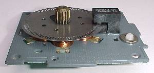
Screw drive is yet another carriage positioning mechanism. The screw drive runs the whole length of the carriage turned by a motor at one end and a thread under the carriage moves it back and forth. In principle it looks as though the screw drive should give very precise head positioning. This would be particularly helpful in printers that could print a character at a time - like typewriters and teletypes, and in printers used for graphics. Large printers stopped using this approach years ago. Making the screw shaft was probably expensive and to make it free running there had to be bearings and a little bit of play in it. The screw slots collect paper dust and running becomes uneven. The screw shaft is still seen in small printers - notably the kind used in POS applications.
One attractive feature of screw drive is that with a dual spiral thread the motor can continually turn in one direction whilst the carriage travels back and forth. Unfortunately this mechanism seems to break down if carriage movement is rapid.
Rubber belt drive doesn't look very efficient but it tends to have better wear and dust-shedding properties than any other approach. Car manufacturers use the same approach in the timing chain which also needs to deliver a limited amount of power quite precisely.
The carriage motor has to deliver the power to accelerate and decelerate printhead, belt and it's own armature - ideally several times per second. This would be relatively easy if the mechanism could use a really big spring, pendulum or circular action. Curiously nobody seems to have tried bending the paper into a half cylinder and having two or more serial printheads spinning on a disk.
The tennis-ball action of scanning a printhead back and forth imposes some strain on the motor.
The carriage motor and its drive chain (belt, wire, cog or screw) also need to position the printhead accurately - to within a tenth of a millimetre if the print resolution is 250 dpi and ten times better on a 2500 dpi inkjet.
Printer makers have used both stepper and DC encoder motors for carriage drive.
![]()
Stepper motors are adequate for small printers with no particular pretence to high throughput. Using a stepper motor the control microprocessor dictates what the motor drive coils are to do and the armature moves accordingly. Actually the motor movement woks well within parameters. If the instructions are too rapid or have to overcome dirt on the carriage bar the motor could miss a step. Control software has to make some assumptions about what it is dealing with in the acceleration pattern.
Printer makers usually put an opto-sensor at the carriage left and when the printer starts it does a slow step left until it sees the opto-sensor change. The processor now knows where the head is in subsequent work. In some printers this is good enough and the printer never looks at the sensor again. Other printers have sensors at both carriage left and right so if the processor loses track of the head for any reason it can quickly egain it.
Quite unimpressive steppers have been used in some fast printers like the dual-head Newbury Data 680. Careful design brings the best out of a motor.
![]()
DC encoder motors tend to be used in more powerful printers like the old MT 490 and the OKI 393. The DC encoder can use its slots to feed back speed information to the motor control circuit. In some circumstances printers using an encoder can tollerate obstruction of the carriage motor and still print correctly - one or two will even make an attempt at printing if you unplug the motor and push the printhead along by hand.
Sometimes the circuitry for motor control is quite elaborate with some element of speed control. In practice this often proved unnecessary and the control circuit simply has forward, off and reverse states and alternating between these rapidly gives very close control over motor positioning.
Of course it is perfectly possible to add an encoder onto a stepper motor. This allows the processor to issue instructions to drive the coils and then see the resulting action happening. Current stepper motor / driver designs don't seem to make this approach very cost effective.
The encoder slots can also act as interrupts telling the processor to feed a new dot pattern to the printhead. The idea of having a slot for every dot position sounds attractive but it creates problems. One eason for using a dot matrix is flexibility, to be able to print different fonts and graphics. If the opto-encoder slots suit 10 character per inch print then they may not suit slightly overlapped dots for 12, 15 or 20 CPI. Some older printers had different encoder markings for different tasks but these days the encoder's indication of position is turned to dot diring patterns in software.
Other Options.
Steppers and DC motors seem to be the only options for carriage that have been given much consideration but there are at least a couple of others - voice coils and liner motors.
Voice coil drive might put a fairly powerful coil at either side of the frame or under the carriage and use it to accelerate and decelerate the head. The width of a printer carriage is rather long for a single voice coil although some old disk drive voice coil mechanisms had a throw of about 100 mm.
One kind of linear motor can be envisaged as an ordinary motor with the coils spread out along a track. As the carriage comes close to a coil it activates accelerating it forwards, then cuts and reverses to repel as it flies past.
The obvious objection to a linear motor in a dot-matrix printer is that if your going to spend money on loads of coils across the pagewidth it might as well be used to work print pins in a shuttle printer rather than move a carriage. This objection doesn't hold for inkjets.
The print process can run both when the head is moving forwards and when it scans the other way. Traditionally typewriters printed only when the carriage was moving forwards because it would have been mind-bending to ask a typist to work backwards. For a logic device working backwards has no cost. Instead of counting up through the print-column positions in memory it justs counts down. Working at maximum speed the horizontal motor would take nearly as long to return the head left as it took to pull it right. (the motor might be able to move the printhead fractionally faster if it is not printing as it goes left) Bidirectional print can nearly double print speeds. There is a problem with any play or elasticity in the drive mechanism because the tension is different in each direction so the dot positions change slightly. Printers often use bi-directional print for high speed work, but switch to uni-directional for high quality work.
High quality bidirectional print using a rack and pinion might potentially be better than with a belt because there is less flexibility in the drive chain. The benefits are academic for dot-matrix printers because no-one is likely to use them for high quality graphics any more. HP use belt drive in their inkjets accompanied by an encoder strip across the carriage width so the pattern-making electronics knows where the head is.
The pins in a dot matrix printer need to apply just the right amount of energy to the ribbon to transfer ink onto the paper. In a perfect world the pin might just press against the ribbon where needed so there might be little or no gap between pin, ribbon, paper and platen.
In practice there usually needs to be a bit of separation between the components. This allows a clear separation between ribbon and paper.
Being fabric, the ribbon's dimensions are slightly uncertain so a gap ensures that no ink transfers where it isn't wanted. The ribbon-paper gap is usually maintained by the ribbon-shield.
The pins themselves are usually given a momentum rather than just a momentary force. The pins fly forward, impact on the ribbon, paper and platen then recoil. This gives a rapid action and a point contact even though the carriage is moving across the page.
The printhead gap has to be adjustable to deal with different thicknesses of material. Most printing is probably on 80gm paper - but some users want a much heavier grade. Labels on a backing sheet may be thicker than most paper. One of the benefits of impact printing is the ability to make carbon copies and 5 layer multipart is obviously rather thicker than ordinary paper.
There are several ways printhead gap can be controlled.
Moving the guide-rail up or down a bit allows the whole printhead to tilt back and forth on its rail. Tilting the head opens the gap between it and the platen.
The main rail can have an off-axis milling at its ends. Rotating the ail moves it towards and away from the platen. This seems to be the most popular solution.
The printhead itself can be slid or screwed forward and back on the carriage - this is rarely seen on recent printers.
The printhead can be lifted to position by compressed air - this was only used by printer manufacturer Facit on one rather extraordinary model.
Setting the Gap on most printers is a manual adjustment - there is a lever on one side of the chassis with a little graduated scale for how many parts the stationery has. Don't take too much motice of the scale, because the printer manufacturer had no way to know how thick your paper is. To load paper move the printhead as far as possible away from the paper. When the paper is in place close the gap until the printhead and ribbon just don't touch the page. Do a test print. If the ribbon is scuffing the page the head is too close, back it off a bit. If the print is faint or uneven the head is too far back, move it forward a bit. Some people mark the optimum position with a drop of Tippex or a felt tip pen - but be prepared for it to differ depending on the paper.
Some printers have a motor controlled carriage that does all this for you (The Epson LQ2550 for instance). Whilst this is a nice touch the sensors to do the job become a potential point of failure.
The printhead sits on a moving carriage. The bulk of the electronics in the printer body has to communicate with the printhead and they tend to do this using a flexible cable. A nine needle head needs ideally needs nine seperate circuits - eighteen wires and connectors. A more frequent wiring is to have nine wires and one high current common return.
Until the 1980s printers often used fairly conventional wire with the lay of the wire controlled in a flexible spring. Even high-flex 40 strand wire would ultimately wear out - in fact everything does. Older printers often have a lot of nasty little repairs in the wire where service engineers found they couldn't get the right wire from the manufacturer.
Almost all recent printers that need a moving carriage use a flat flexible "membrane" cable. This is usually solid but very thin copper tracks in a white plastic. The connection to the printer base is usually somewhere near the middle of the printer and usually folds to left or right and then doubles back into a connector on the carriage.
Over time these flat cables do fail - the copper conductors break up and the plastic coating wears out.
On older printers there have to be enough conductors for each coil to have a seperate supply and a common return. This wiring driving the inductive coils in the printhead is almost inherently electrically noisy. Designers improved it over time. Having paired wires to the coils should reduce electrical noise.
Later generations of printer have more things on the printhead - more pins, but also thermistor temperature sensors, colour ribbon lifts, even a fan to cool the printhead down. As the complexity grew so did the number of circuits so there could be two twenty-way carriage cables - ather a lot to go wrong.
Inkjet printers tend to solve this by using SerDes circuits. Information to be communicated to the printhead is turned to serial on in the main circuit, relayed up to the head, then deserialised and fed to the drivers. There is a cost in having a fairly complex circuit on the carriage and a benefit in having a much simpler carriage cable.
So far as is known nobody has yet used a fiber optic or wireless link to the carriage - after all it would still need electric power. Of course the carriage could get power from:
- the carriage rails via a brush
- or if it had a carriage width linear motor from the drive coils.
End-stop detection.
Carriage width encoders
--
© Graham Huskinson 2010