
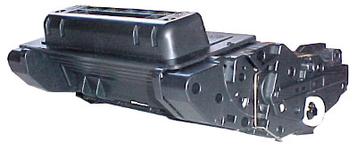
HP Original Cartridges
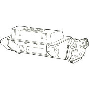
HP intend the print cartridge to change about 70% of the parts in a printer that wear out and are likely to fail. HP original cartridges are the most reliable replacements (it is almost impossible for re-manufactured devices to equal them). If you have a "questionable" fault then a new HP cartridge is a good starting point.
The P4014, P4015 and P4515 were replaced in HP's lineup by the M601, M602 and M603 printers in 2011. Those printers look almost identical from the outside and are similar internally.
In 2015 the M601 series are in turn being phased out in favour of the M604, M605 and M606 series. if you prefer to replace rather than repair then the price of a new machine might be gauged from the following:
Low-end
Big printer with networking. Replaces the P4014.
-
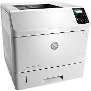
E6B67A HP Laserjet Enterprise M604n
Please email us to confirm availability
A4 Mono (B&W)
LAN, USB
5,000 - 13,000 pages/month
10,000 page cartridge
Mid-range
Networking, Duplex print and takes the big 81X catridges. Replaces the P4015.
-
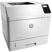
E6B70A HP Laserjet Enterprise M605dn
Please email us to confirm availability
A4 Mono (B&W)
Automatic Duplex
LAN, USB
5,000 - 16,000 pages/month
25,000 page cartridge
High-end
Networking, Duplex print, extra cassette tray and the touchscreen control. Takes the big money-saving 81X catridges. Something of an advance on the P4515 and M603.
-
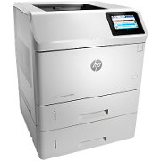
E6B73A HP Laserjet Enterprise M606x
Please email us to confirm availability
A4 Mono (B&W)
Automatic Duplex
LAN, USB
5,000 - 20,000 pages/month
25,000 page cartridge
There are 7 models in the range.
Disadvantages of replacing the P4014 and M601 are that new printers take different cartridges and accessories. There is no very convincing print advantage from the new machine either. Advantages are in network security and flexibility - new printers have NFC (Near Field Communication for printing from SmartPhones).
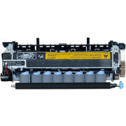
Maintenance Kit
The P4014 and M601 series are highly repairable. Most faults will be fixed by either an new cartridge or a new maintenance kit.
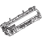
Fuser
Repairing the HP P4014 and M601 Series .
(Phase 1 of 2)
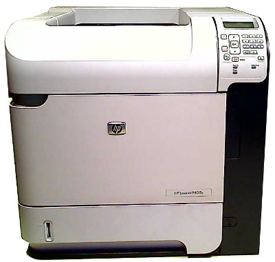
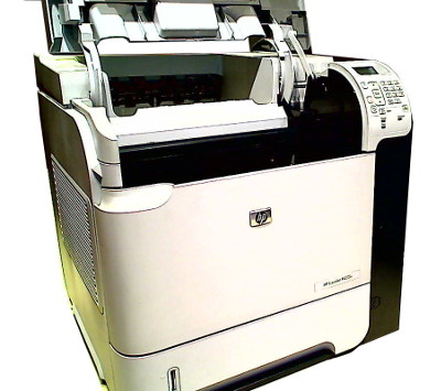
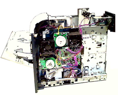
The HP LaserJet P4014, P4015 and P4515 all look similar and not surprisingly there is no difference between them in terms of dismantling to get at components. The P4014 has all white trim whilst the P4015 and P4515 have part black plastic. There is some difference in the plastic case parts as the P4014 uses different plastic mouldings to preclude use of larger cartridges.
Part numbers given here are generally for the P4015 printer. That is the model photographed being dismantled, and possibly most common in the field.
The P4014 series are very similar to the LaserJet M601, M602 and M603 in overall construction so this section can apply to either.
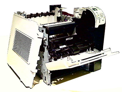
First stage in dismantling the printer is to take the cartridge out and put it in a dark dust-free place - such as in the light proof bag in an old cartridge box. On site there is a needs-must problem - in a bin bag inside a cardboard box is one solution (not static free though! )
Most Repairs Don't Need Dismantling
Many faults with these printers will be cured by changing the cartridge, so unless you are certain the fault is somewhere else do that first. Opening a new cartridge should not be "wasting it" (as might happen with an inkjet) since these laser printers are almost invariably repairable. Keep any part-used cartridges in the bag, sealed with sticky-tape in the box and in a cool dark space. Cartridge drums are light sensitive and their properties decline if left exposed for as little as an hour.
Paper Jams and paper feed faults are most likely to be the soft rollers. These can be replaced at low cost with a feed repair kit. Rollers just slide onto their shafts, see here
Blotches on the page that are not explained by the cartridge are most likely to be the fuser. These printers are a little unusual because the fuser is easily removed (see below). The printer will prompt for a "maintenance kit", which includes a fuser, a little beyond 200,000 pages.
Before setting out on any repair its a good idea to check the printer's own error log which is visible through its internal Web Server at the printer IP address. See the summary here

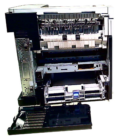
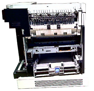
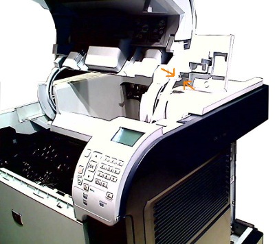
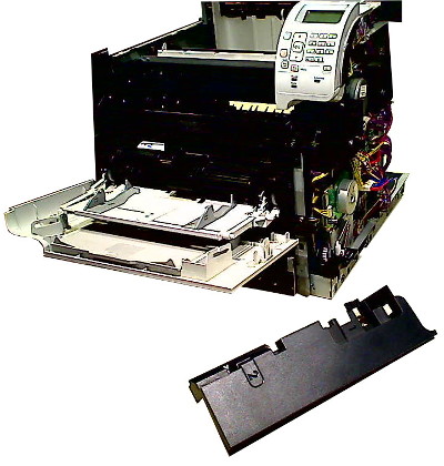
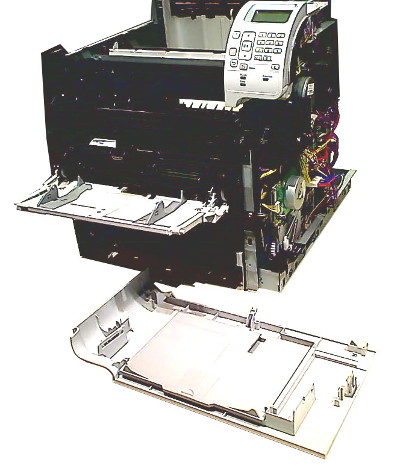
Most printers come with a duplexer - hence they are "DN" versions (duplexer, network). The duplexer slides into the rear, to remove it lift slightly and it should easily slide out. There are also "X" models that have an extra tray, the printer just sits on top.
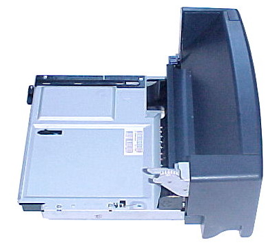
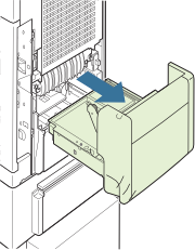 |  The duplexer is a slide-fit into the rear of the printer. The duplexer cogs push a pendulum assembly that disengages the printers ordinary exit path, the duplexer motor catches pages as they are about to exit and pushes them back down, round and into the registration station. |
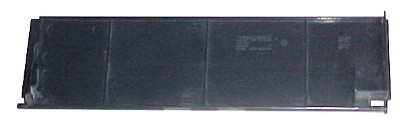
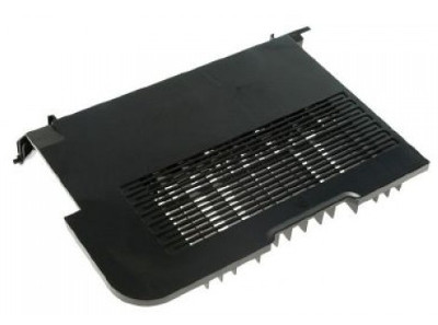
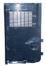
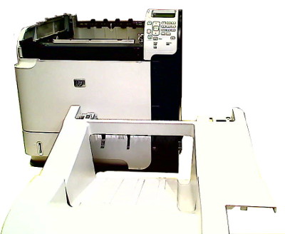
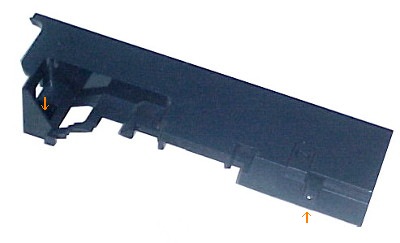
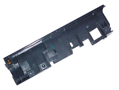
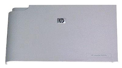
The "legal cover" has to come away at some point, it hooks onto the case side.

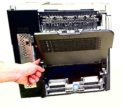
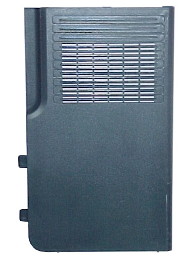
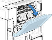 | The rear door or "face-up tray" lowers and removes with finger pressure into the left hand arm. Plastic bosses stick into the metal of the chassis - ( its a bit crude but works). Observe where the two hinge-points are - there is something of a guide moulded into the chassis metal but nothing very clear. |


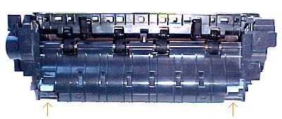
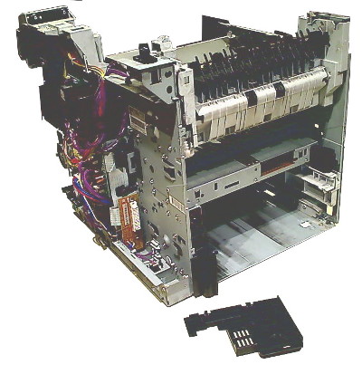
To remove the fuser push up on the blue latches whilst withdrawing the fuser from the rear of the printer. A bit of gentle wriggling may be needed to get it free of the connector socket on it's inner face.
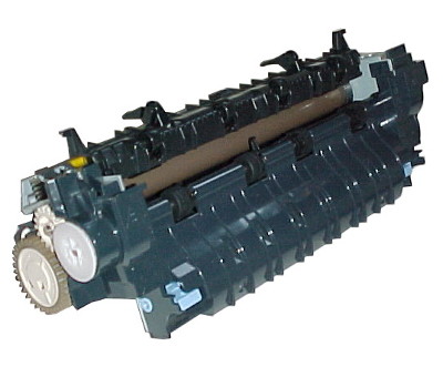
The fuser exit assembly can be opened to look for damage to the sleeve. Turn the sleeve using the big brown cog as though it was feeding paper - it is stiff - there is a very substantial load from the pressure roller.
 |  |
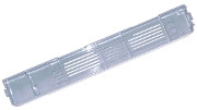
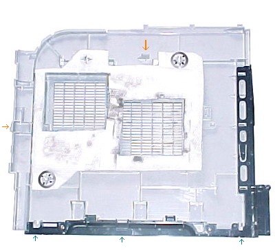
The formatter cover sides off to the rear.
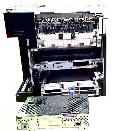
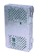 | 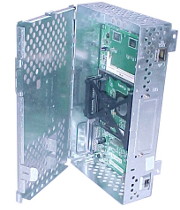 |  |
The formatter is held by two thumbscrews and slides out to the rear. The formatter is a scattering of memory, Ethernet and USB support chips around one large PMC-Sierra chip. The formatter itself does not seem to be a significant source of problems. The printer should report error "79.xx" if the formatter fails. Firmware is a known source of problems but that is changed by uploading another ".RFU" file ( ie an updated firmware). Only HP can supply firmware - don't download it elsewhere.

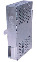
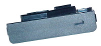
The option cover at the top rear of the printer just unclips upwards.
This is the point in disassembly where ordinary users stop. Further work means wielding a screwdriver.
Removing the Covers
There is nothing obtuse about working on the P4014 or M601 series printers so workplace based and field service technicians will have no difficulty. Users venturing into the field need to be aware that printers are not like PCs - high voltages are present if the device is plugged in, the laser is a possible hazard and the motors could be. You are at risk from the circuits. The circuitry is at risk from your handling it. Manufacturers often put "no user serviceable parts inside" stickers on equipment. Actually there are parts in this printer that a knowledgeable user with a tech-support background can change.
Tools recommended are
● #2 Phillips screwdriver with a magnetic tip and a 152-mm (6-inch) shaft length
● a small flatblade screwdriver, sometimes called a terminal screwdriver.
● Needle-nose pliers
● An anti-static strap
The screws are mostly M3 and M4 sizes in silvered and Japan lacquered types.
To remove the covers, first disconnect the cartridge door link arm. The service manual says to use needle nose pliers but practice shows it can be done with finger-nails.
The paper cassette tray probably needs to be removed since it is likely to be in the way later.
The only large assembly visible with the top cover away is the laser scanner unit. It has a hazard warning saying "Invisible laser radiation when open. AVOID DIRECT EXPOSURE TO BEAM. (It also says "Class 38"). Curiously they haven't used the laser-beam sign but just an exclamation mark in a triangle.
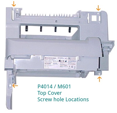
The top cover is held in place by four screws, two at the rear under the output accessory cover and two visible with the cartridge door lifted. With the screws out the top cover lifts away.


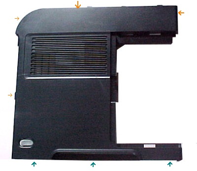
The right cover is held by one clip in the top middle and another at the rear juncture with the right-rear cover. With these released the cover folds down away from the metalwork on hinge points along the bottom. A little effort is needed to overcome the tabs at the front.
The significant release tab for the left cover is inset a bit and engages a slot in the metalwork. Push it down. The side folds down but needs a bit of wiggling to clear the curved MP tray front cover.

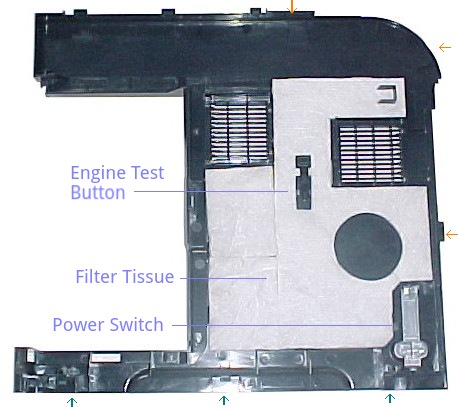
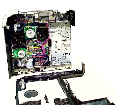
The left side visibly contains just the two fans and the thermistor. Invisibly running up the inside of the metalwork between it and the cartridge guide are spring-metal rails carrying the high voltages and the antenna signal.
The right rear cover just unclips from the metalwork.
The right front cover is more trouble. First remove the envelope feeder cover marked with a number "1" as it is over one of the screws. There are three screws and a clip holding the cover in place.
With the right front cover off it is at last possible to push the front-cover and MP tray outer to the right and off it's hinges. The first stage is to ease the bosses on the MP tray out of the slides on the cover - which is quite a treacherous job because the slides easily get broken - which is also often the reason for replacing the cover. Once they are out, the cover slides to the right and off it's hinges. This completes removing the covers.
Dismantling the covers more or less has to follow the sequence: accessories out, top off, right side off, right-cover off, and then front cover. Each interlocks with it's predecessor. There is no particular point in taking the left cover off unless you want to get at the fans and thermistor but it isn't difficult.
Next Section - removing the innards here.
Copyright G & J Huskinson & MindMachine Associates Ltd 2013, 2015. Some pictures derived from HP User and Service guides. These technical pages do not constitute an offer for sale; just our knowledge at the time of writing. See the catalog. Sales pages on this Web site use cookies to store user information. We also use Google Analytics to track site usage patterns.