
Details of the HP P4014 and M601 Series Innards.
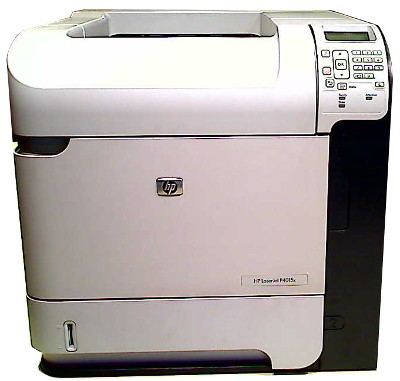
The LaserJet P4014 series and M601 series are similar in external form but somewhat different internally.
The paper pickup or "main" motor, drum motor and DC controller differ greatly between the two models. The fuser motor is (almost) identical and so are the layout and principles.
The " phase-1" page showed how to take the cartridge, cassette, duplexer and formatter out, get the top off and the side panels removed. This involves just nine screws - two thumbscrews for the formatter, four for the top and three for the front right panel. The side panels are secured by clips.
The rest of the job is entirely a matter of screws.
Tools recommended are
● #2 Phillips screwdriver with a magnetic tip and a 152-mm (6-inch) shaft length. A few tasks might benefit from a short shaft.
● a small flatblade screwdriver, sometimes called a terminal screwdriver.
● Needle-nose pliers
● An anti-static strap
The screws are mostly M3 and M4 sizes in silvered and Japan lacquered types. Note that the lacquered screws can have a tight grip.
Every device has a connector going back to the DC controller. HP say Do not pull directly on the wires to disconnect them. Always pull on the plastic body of a connector to avoid damaging the connector wires.
They do not say how you can achieve that given that the plastic body of most sockets is almost entirely surrounded by the plastic body of the circuit board plug. Bull nose pliers or forceps might grip but experimenting suggest sufficient pressure can damage the plastic. If its a ten way connector grip all ten wires at the socket and a firm tug frees the connector. Note that half the connectors have a securing latch that needs to be held out of the way.


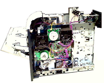
The pictures above show a P4015 with the sides removed - phase 1 in getting at the works.
Control Panel

The front panel is held by three screws, the middle one having a star-washer for grounding. With the screws undone moving the panel slightly rightwards releases it. The main problem might be the wire harness which seems to be under the drum motor and lid switch wires.
The control panel has it's own microprocessor and is electrostatically sensitive; wear an anti-static strap or touch the chassis before handling it. that goes for all the electronic components in the printer.

Control Panel for the P4014 is RM1-5060. The P4015 and P4515 use RM1-5059 (with number keys).
Control Panel for the M601 is RM1-8290 and for the M602, M603 the numeric key panel is RM1-8289. P4015 and M602 panels differ in key labelling and probably in protocol.
Right Side Fans
Fans inevitably wear out and then become noisy or jam.
The fans clip in. FN102 RK2-1992 and connector J79 on the DC controller is in the duct to the right of the drum motor. FN103 RK2-1989 and connector J75 is to the left.


The fans seem to be identical except that one has a longer lead to reach across the DC controller board.
Both fans blow inward; there is an airflow arrow moulded on the fan housing; (they will fit the wrong way round but not work properly).
These fans seem to be longlived (unlike those used on PCs), however anything mechanical needs changing from time to time.
RK2-1992 Axial Fan for rear of cartridge bay.
RK2-1989 Axial Fan for front cartridge bay. Both fans are used in the whole print family - P4014, P4015, P4515, M4555, M601, M602, M603, M604, M605, M606 and M630.


RK2-1989 fan removed
Pickup and Drum Motors
The paper pickup motor (- manuals sometimes say "main motor") is at the lower front secured by three of the black screws to the back of the paper pickup drive gear assembly (marked orange below).


The motor may be labelled RM1-5066 but in the service manual and most web-sites selling HP new parts it is RL1-1657.
The drum drive motor is likewise secured by three screws to the back of the drum drive (marked purple above).


The motor may be labelled RM1-5052 but in the service manual and most web-sites selling HP new parts it is RL1-1659.
These "outrunner" motors are used in the LJ-P4014 series but the M601 and M604 use a completely revised motor in these positions.


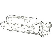
RL1-1659 drum motor removed. It is not unknown for the helical drive cog to split. This should give a motor error.
Paper Lift Motor
Paper in the cassette is lifted by motor RM1-4585 set into the right mid base of the machine. Getting at it requires two of the plastic guides to be removed, one is the pivot for the motor and the other a wire guide holding leads going the formatter. The motor is spring-loaded against a cog on the cassette by a spring at the top ( RC1-0198). Remove the spring first and put it in a safe place - it is a known escape artist. The motor is still pivoted on a guide rail inside the chassis. To get the motor out of the recess it can be lifted from inside the cassette space, angled and pushed out below the DC-controller. A flashlight may help.


This motor is used in the P4014 and M601 series. (The motor from an LJ-4200 looks similar but may not be. M604 series uses RM2-6335, again similar in appearance.)


DC-Controller
The DC-Controller is the microprocessor that controls the print engine. Historically these boards housed the drive transistors for motors and solenoids and this one still has some, but the motor driver chips are mainly on the motors themselves. This board mainly deals with input and output logic signalling. Although they do so much DC controllers aren't notorious troublemakers. However in this case the board is over the fuser motor so if that needs attention it has to come out.
The board needs careful handling for four reasons. First it is soldered to a flat-flexible cable (FFC) that holds the formatter socket - a slightly nasty kludge but it works. The blue and yellow power leads are soldered as well. Second it is absolutely covered with the sockets that connect every other part of the printer. As mentioned above it isn't easy to remove the connectors without tugging at the wires. We recommend a firm grip on all wires right up against the socket. Note that many but not all sockets are unique. See the page on the DC controller for what fits where. And just a reminder, it is static sensitive!

As per usual the labelling on the DC controller is different to that in the Service Manual. The DC controller says RM1-5047 and RM1-5049, neither of which are found in HP PartSurfer. The service manual says it is RM1-4582 (now RM1-4582-090CN so there have been a few revisions).

The DC controller rather exemplifies modern electronics. Almost everything is done by a single microprocessor and the remainder of the device is power regulation , solenoid switching and the mass of interconnects with the motors and sensors.
The main chip is marked RK22005-03
and MB90F042
. The first number looks like a Canon/HP part number and the second suggests the chip is a Fujitsu F2MC-16F series 16 bit microcontroller "optimized for applications in mechatronics". These devices have a 128-Kbyte flash memory.
The board does have a self-test most easily accessible by the "engine test" button near the top left. If the printer is powered up then pressing this button will set the printer in motion - it produces a page of plain lines. (The lid switch has to be foxed if the printer is dismantled and there is the obvious caution that high voltages and moving mechanisms are exposed ).

Paper Pickup Mechanism
The paper pickup drive is a likely source of feed problems early in the paper feed process that can't be resolved by changing the soft rollers.
Firstly however the main source of grief in the pickup mechanism is the solenoid, RK2-0270, which has the correct part number printed on the armature.This can be removed without taking the entire paper feed mechanism out - which is just as well as stripping the DC-controller and the pickup mechanism out of the printer are not light undertakings.
Solenoids can be fast acting but have a problem with residual magnetism. That is what the little area of springy foam on the coil-former aims to overcome, freeing the armature earlier than would otherwise have been possible. If the armature timing becomes bad a likely sign is that the printer double-feeds then jams. Printing perfectly well single sided but jamming in duplex is another possible fault cause by timing issues - and likely to be blamed on the duplex unit but perhaps not cured by swapping it if the real fault is in paper pickup timing.

How the solenoid mechanism looks inside the paper drive housing. It releases the cam one turn of which lowers then re-raises the pickup roller and runs the feed-roller sufficient to move paper to the hard feed rollers in the paper throat.

The pickup mechanism is a moderately elaborate piece of clockwork (shown with motor and gear re-attached)
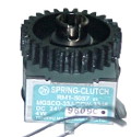
Clutches used to be a notorious source of problems in early laser printers - but that mantle seems to have passed to the solenoid. Although the clutch has a part number (RM1-5057) it doesn't seem to be listed as an official HP spare although some brokers do list it (possibly getting it from surplus printers? ). It is necessary to take the paper pickup drive out to get at the clutch.
The exact function of the clutch is a bit elusive. The paper feed (main) motor drives all the cogs above the motor continually (they are just below the left hand fan). They work the hard pickup rollers in the throat and the registration rollers. Below the paper feed motor there are a couple of gear-down cogs and then the clutch. When active, the clutch drives the rest of the cog-chain in the pickup mechanism and in any accessory feeder units. However other than that a few more cogs would turn if the clutch wasn't there it doesn't seem to play much part in the greater scheme of things - possibly let the motor get to speed without a load? … If the clutch slips no paper input device will work except the MP tray, which has its own clutch.
To get the whole paper pickup drive assembly out it is first necessary to remove the motor and DC controller, to get the power-switch rod out of the way and the cable guide at the bottom right. Take the spring clips off the back of shaft RL1-1658 as it has to be pulled out.
The paper drive assembly has at least three connections through into the paper paths:
Drive to the paper feed rollers is the RM1-4562 paperfeed shaft Z assembly worked by cog RU5-0045.
To prevent double feeds the printer also drives a roller in the cassette tray. The shaft for this protrudes from the paper pickup drive, through the right-wall of the printer into the cassette tray space and has to be removed. It is secured by an "E" ring, two spring arm clips, two springs and a bushing. The cog and shaft can be can then be withdrawn into the tray space. The drive cog will fall off the shaft but probably not out of the paper pickup mechanism.
Screws securing the assembly can now be removed. The assembly is still not free to lift out because of the hook on the Z-assembly lift plate holding the rollers, lift the back roller in the tray cavity and the mechanism will come free and can be lifted out intact. Be aware that one or two cogs are not captive and will fall of their shafts if allowed. The RM1-4532 page aims to explain its workings in detail.
Also beware of the grease. It is no surprise to find a gear chain is greasy but whoever has the factory grease gun seems to be squirting it copiously and at some odd surfaces.


Fuser Motor
The fuser motor RM1-5051 is under the DC-controller and also the cable guide so they have to be removed. It is another "outrunner" motor working a short gear chain. Most motors seem to be labelled "RM1-5064" - but that isn't in the Service Manual or HP PartSurfer. It will be no surprise (in view of what has already been said) that the first number yields HP original parts and the second eBay and similar vendors. Judging by research in Google images there was an early version RM1-5015 with a big through-hole mounted SLA5212 driver chip.
Whilst HP changed the paper pickup and drum motors when they shifted from the P4014 to the M601 series they kept the fuser motor so the same device is used in the P4014, P4015, P4515, M4555, M601, M602 and M603. At the time of writing we haven't had reason to take a motor out of an M604 series printer but it certainly is in the same position, looks pretty much the same but appears to be labelled RM1-8928 - which is actually the same number given in the service manual (wonder of wonders).
Issues with fuser drive are more likely the gear chain RC2-2432 than the motor. The final gear can be seen with the fuser out. If there is more than a fraction of mess on the metalwork around the gear may have been grinding due to the fuser not seating correctly.


Drum Drive Unit
Taking the drum motor off was covered above.
The drum drive rotates the organic photoconductor drum in the cartridge and it in turn drives the transfer roller via its blue cog. The assembly is RC2-2484 and that is stamped in large letters on the metalwork.The drum motor white helical toothed gear engages a large white 193 toothed gear which takes up most of the space in the drum-drive housing. The drum motor gear is a known failure point because the mechanical load of turning the drum is substantial, gears can split. HP don't provide new gears directly, just with a new motor. We have seen at least one clone manufacturer making the motor gear.
The drum drive cog drives a boss with a triangular recess in it matching the drum axle on the cartridge. The boss sits over a couple of ramped cams, one of them connected to the lid release arms. When the cartridge lid is open these levers are pulled up, one of the cams rotates and the boss withdraws from the cartridge. When the lid is lowered the lever pushes the cam round an a spring pushes the boss back in. A broken release arm will mean the cartridge can't be removed. The difficult of repair depends on which one has snapped or fallen off.


For a top or front-loading cartridge to get in and out of the printer something must engage to drive the drum and other rollers. Early cartridges might push onto a cog at the lower part of one side, but this relies on the user reliably loading the cartridge in such a way that cogs mesh. Otherwise the lid won't close or gears will grind badly.
These printers use an axial thrust bearing. When the cartridge lid is opened a linkage from the lid rotates a ramped cam and a shaft is pulled out rightwards out of the side of the cartridge. As the lid closes the cam and ramp move the other way and the drive axle boss is re-inserted into the cartridge. Movement of a few millimetres but is sufficient to engage or release the cartridge.

Paper Feed and Power Supply
The paper feed and power supply are screwed together and insert into the back of the printer under and behind the fuser. There are screws securing the power supply on both sides. The power supply carries lots of trailing cables - some for power, others for control both in and out (HV circuit control and sense) for instance. These cables run along a guide and out of the right side of the printer. On the left hand side are the HT connectors but HP have been a bit clever there and they are made of springy metal that disengage as the unit is pulled out.
The bulk of things is the power supply RM1-4578 for 220 volt versions of the printer. The power supply does not seem to go wrong much which is good, because getting it out of the printer is difficult. Testing the PSU once it is out almost an impossibility - it does too many things and has so many connections.The bit likely to go wrong is the paper feed belts which are not meant to be touched much and so they are quite fragile. Presumably they get broken when people make ill judged attempts to pull paper backwards through the fuser rather than going to the back of the printer and removing it - or the whole fuser. One of the fragile bits of the machine being difficult to change is a bit of a nuisance. The little bail-rollers at the front of the thing are exceptionally cussed particularly when the thing is out of the machine - they will break lose and disappear at the slightest provocation. If you take this object out of a printer put it in a sealed polythene bag so the little rollers and shafts can't get away.

The purpose of these belts is not entirely clear. Obviously they carry paper from the transfer roller to the fuser and short media wouldn't make it from the registration point to the fuser alone. The belts don't seem to apply much power to the paper though and the pattern is wierd. We have been told that the printer will work single-sided but not duplex with them broken or removed. That seems odd - at this point in the paper path why should that make a difference?


Paper Feed Drive Assembly

The paper feed rollers in the printer throat, at the registration point and the MP-tray are driven by an assembly of four cogs supported by metalwork labelled RC2-2541. These stubby cogs protrude through the right wall so that those on the feed rollers connect. Cogs and rollers turn continually with the paper feed motor running - no clutch disconnects them.
It seems vanishingly unlikely that these would go wrong however toner mixed with grease builds up if the printer has dealt with a lot of leaky refilled cartridges. Paper feed assembly RM1-4532 has to come out to get a clear look at them.

Multipurpose Frame

The multipurpose frame RM1-4563 forms the majority of the front of the printer. It not only provides the multipurpose tray pickup mechanism, its inner surface is part of the printers paper-path throat. Getting at the feed rollers and opto-sensor in the throat and wear in this area causing jams might be a reason to remove or even replace it. Because it is important that the frame doesn't move it is secured to the printer by eight screws: four into the metal frame and four onto the plastic RC2-2269 transfer block. The covers need to be removed before it can be moved but there is no need to take off parts from the right hand side.
The outer MP Tray / front cover needs to be removed but the inner one doesn't - although if it isn't then at the left side the support arm falls off and it does hang lose from its springs. The whole thing is a big assembly containing the MP tray lift cams, the roller drive shaft as well as the control solenoid and MP paper detector.
The left hinge arm will fall off at the slightest provocation the right hinge arm can only be removed by taking off the right nip-guide which is only secured by one screw. However the cogs on the right hand side then tend to come unseated.
If the MP tray is taken off its springs then there may be a bit of trouble getting them back unless you use forceps. The springs are under covers at each side which will pry off. Springs can be put on the tray first and lifted into place with a couple of little screwdrivers.
The multipurpose frame's cogs take mechanical power from the same RC2-2541 four-cog assembly that drives the feed rollers and registration rollers. The drive cog is in two halves and parks with a gap in the teeth facing the drive cog until the solenoid releases it.


Feed Rollers

The feed roller set in the throat are RM1-4527which are two fairly hefty steel rods each with two rollers.The inner rollers are hard rubber, the outer rollers something like nylon. The inner rollers are driven by a cog that engages continually driven cog-set RC2-2541. The outer rollers are clamped to the inner by steel helical springs stretched across them.

The feed roller mechanism is held to the transfer block RC2-2269 by four screws - so having got the multipurpose frame out of the way it is easy to change.
The drive cog incorporates a ratchet. The purpose of this seems to be that paper can be pulled upwards from the cartridge bay easily - it won't move so easily backwards.

Registration Rollers


Copyright G & J Huskinson & MindMachine Associates Ltd 2013, 2015. Some pictures derived from HP User and Service guides. These technical pages do not constitute an offer for sale; just our knowledge at the time of writing. See the catalog. Sales pages on this Web site use cookies to store user information. We also use Google Analytics to track site usage patterns.