


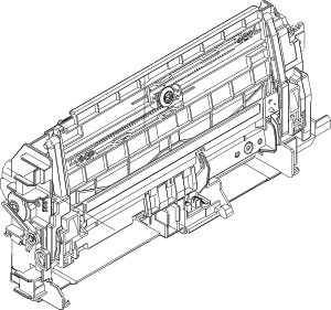
HP RM1-4563 Multipurpose Pickup Assembly for HP P4014 Series Printers.
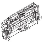
HP part RM1-4563 is the Multipurpose Pickup Assembly; the entire front inner of the multipurpose fold down tray.
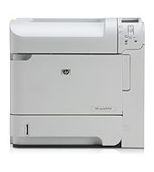
RM1-4563 is only used in the P4010 series, P4014, P4015 and P4515 - a different part RM1-8425 is used for the LaserJet Enterprise 600 M601, M602 and M603. (It's not very different, almost everything in this description remains true).
The part is a black plastic assembly containg the cogs, shafts and wiring for this part of the printer. The solenoid and a sensor are included.Most sources suggest it also has the first part of the white fold down tray with the slideable paper guides and the pickup rollers (Part RC2-2336). This is certainly what is shown in the service manual. Google images are a little inconsistent and HP could change that with variant numbers, and it may depend on whether you buy an HP new original or a "refurb". (These are not things that ship in huge numbers.)

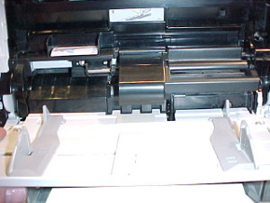
The MP tray mechanism part dismatled showing the position of the three pickup rollers above the middle of the tray. They push paper up a little and into a slot not visible here. The visible slot is for the optional envelope feeder.
The only reason surplus vendors might not ship the whole thing is that it is oddly unstable. The right hand arm of the inner tray is attached to the main body unless you remove a couple of screws and covers. However the left hand arm is determined to spring away from it's cam and fall off. HP appear to tape arm and tray down withe their characteristic orange sticky-tape.
Replacing the entire RM1-4563 rather than just the rollers is usually an approach to something getting damaged or a matter of speed rather than spending ages diagnosing the specifics of a fault in the cogs.
We strongly suggest replacing the three pickup and feed rollers using kit CB506-67905 before establishing a need for the whole pickup assembly. HP don't make individual parts of this assembly available - brokers might. There may be enoguh information here to help you amke good units by triage from several printers.
The MP tray operates quite differently from the cassette. Where the cassette has a tray lift motor the MP tray does not. The tray plate is normally held down by cams but rises up on springs as the pickup roller acts.
The assembly looks quite complex because it is acually several things in one frame. Fitting it is not such a bad job as it may frst look. To fit it you will need to remove all the printer covers - top and sides. Remove eight screws and disconnect wires for solenoid and opto-detector from the DC controller. It's a job for a technician, not an end user - although it isn't terribly complicated. The service manual may be helpful. We set out some instructions with pictures here. We suspect some people may need to buy these parts to get components of the tray that get broken - or turn to refurbished parts. The solenoid for the MP tray (RM1-5055) is not listed as a separate part by HP - oddly inconsistent because that for tray 2 is.
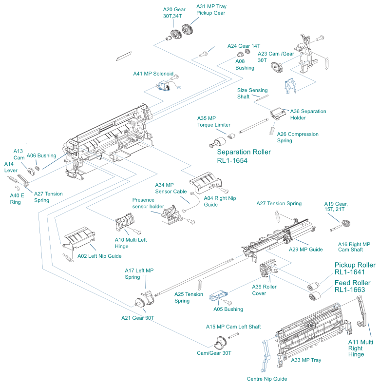
To see RM1-4563 in context in the engineering diagrams click here.

The RM1-4563 unit without its tray. The left arm and therefore the tray fall off when the unit is not in the printer - here three of the four axles can be seen and the cams on either side. Yellow wires come from the opto-detector near the bottom front right and the grey wires from the solenoid at the top right.

The right side tray lift mechanism and its cog-cam. When a sheet feeds the cams rotate and springs lift the tray up so media contacts the spring loaded rollers. The left side is less elaborate.
About the MP tray
Many people never use the multipurpose tray on their printer and some don't even know it is there.
We know people are sometimes puzzled by the MP tray. We sell roller kits and sometimes have conversations that go "these rollers don't fit" - "well we sent what you asked for". It then transpires that they asked for tray one rollers not knowing that on HP Printers tray-1 is the fold down MP tray - not the cassette. For no great reason the MP tray rollers are completely different to those in the rest of the printer, even though they work in much the same way.
From the manufacturers point of view it is moderately complicated to provide an MP tray. Inkjets rarely have one, or perhaps morre accurately their trays are like the laser printer MP tray - small capacity but general purpose. Simple laser printers sometimes just provide a bypass slot - a way to slide an envelope or coloured sheet on top of the existing paper stack.
This MP tray is rather different; it deals with an entirely separate heap of paper and uses it's own pickup mechanism.
In this case the MP tray mechanism is as complicated as that for the cassette, perhaps more so because the MP tray frame also includes the paper lift. HP have packed the mechanism into a space 3 inches thick folded up, which is quite neat for something that operates at a fairly high speed and is expected to handle a greater range of paper than is normal for the cassette. (Hence no doubt the different rollers)
It is probably accurate to call it an MP-frame; the various cogs and rollers are arranged around it and not concentrated in one place as they are with the cassette paper pickup drive RM1-4532.
The MP frame is held in place by eight screws, four into the metalwork of the chassis and another four into the big plastic moulding at the heart of the printer that seems to be called the transfer block (RC2-2269)- it holds the transfer roller amongst other things.
The MP-frame is driven from the group of four cogs on the RC2-2541 metalwork near the top right of the printer. These are being powered by the main motor via a single cog in RM1-4532 and not via the clutch - so that can't be a suspect part in MP tray operation.


Power for a Single Turn

Power takeoff is done by a single turn mechanism comprising some cogs, springs and cams on an axle running through the upper part of the frame from right to left side. This has a a solenoid armature working on a cam with a detent point. The cam is part of a spring-loaded split cog to start things moving. At the other side of the printer but connected through the steel drive axle is a spring loaded lever acting against a cam finishes the action off and re-loads the mechanism for the next action.
Both sides of the spring-loaded split cog has nominally 34 tooth positions but 4 teeth are missing. This mechanism looks like a pair of gears packed side by side; actually they are linked through a spring which will force the inner one to move 3 tooth places when the solenoid releases it. After that jump a tab engages the halves and then they both turn at the same time. This cog-pair doesn't have a part number embossed on it but in the service manual diagram it is A31 MP Tray Pickup Gear (it picks up mechanical power, not paper).
The inner of the pair carries the cam with its detent point. The MP-solenoid armature rides on the cam until it is caught at the detent point. Operation of the solenoid, lifting the armature from the detent allows one turn of the cam and cog.
The cogs wouldn't turn when they were released because the four missing tooth positions have nothing to engage, when held at its detent point this bald spot is facing the RC2-2541 drive cog.
The inner cog overcomes this because of it's inner spring. When the armature (RM1-5055) releases, the spring between the cog halves pushes the inner one around by three teeth, now there is something to engage. A tab on this half-cog also engages with one in it's mate. After a couple of teeth have turned movement of both halves is under way, all of the cog is engaged with the drive cog and turning the steel shaft that runs through the upper part of the MP frame. The inner cog stays three teeth ahead as they turn but both are driving the shaft because the tab on the inner one has engaged the tab on the other.
This shaft drives the cam gears that raise and lower the tray and the feed rollers, which we will come to.
At the other end of the shaft and the left side of the frame is the re-load mechanism comprising spring loaded lever RC2-2370 and cam RC2-2369. Although they are at the other end of the axle they are part of the split-cog single-turn mechanism. Once the cogs have set off this cam gradually lifts the lever against its spring and then just holds it there for most of the turn (other things are happening but these mechanisms just continue round). Just as the the inner split cog at the right is reaching the armature detent point for its cam, the cam at the left end gets to its tipping point, the spring loaded lever forces it round suddenly and with it the outer cog at the other end is jerked forward by three teeth so that it catches up with it's mate, once more compresses the spring between them and presents the bald spot to the RC2-2541 drive cog.

Everything comes to a rest with the four missing teeth of the bald spot facing the drive cog. A sheet has been fed from the tray, the spring cog reloaded, everything is ready for the next turn. (Or that should be true; but if so why are you reading this?)

On the axle alongside the spring loaded cog is another with two sets of teeth. It has no part number but the manual refers to it as A20 Gear 30T,34T
. The shaft is milled to a D section and both the outer part of the split-cog and this are keyed to the shaft so they move in lock-step. Likewise with the gear at the left side.
This gears outer side works the right hand cam gear to raise and lower the paper tray, whilst the inner side which has half the teeth missing works the feed roller shaft.

Tray Lift Cams

There are cam gears at either side of the frame and as they turn they control the rise and fall of the inner MP tray which is lifted up by its springs but pushed down by the cams. The cams have to be aligned with one another and with the drive axle parts properly. It is easy to reassemble the tray with the cams not properly aligned - but that difficulty won't work at all thanks to some offset teeth that then won't let the mechanism make a turn. We assume this has been done to make errors absolute and detectable rather than niggling.
The cam on the left is marked RU6-0139 and it has a bridged double tooth. This bridged tooth aligns with a rim gap in the cog on the axle above it when they are at rest. The metal axle for this cam inserts from the right and goes through the left wall of the frame where the re-load lever is clipped to it.

The cam on the right is marked RU6-0140 and it is "same but opposite". Half way through its turn is a position where two teeth are offset a bit. In the matching cog on the drive shaft three teeth protrude. At rest the shaft cog and cam cog must mesh or they will lock up. To get them to mesh as the shafts turn they need to be diagonally opposite one another when the frame is assembled. A pointer built into the right cam and a hole in the left cam rather suggest there might be a factory jig for doing this. The alternative for the poor bloody infantry is guesswork and checking things work by hand. It is quite easy to release the solenoid by hand and turn the drive cogs to check the action although the amount of grease on a working printer is a bit of a disincentive.


Pickup Assembly Fold-up
There is another gear on the right hand cam gear shaft, this is the rather odd looking thing marked A19 Gear 15T,21T in the diagram
. It shares a shaft with the right hand cam cog but is otherwise unconnected with the other cogs. It's purpose is to transmit the movement of the right hinge to RC2-2347 which carries the rollers. As the MP tray is lowered the rollers automatically lower to hang above the tray. Once again there are double-teeth so that if things aren't aligned they won't work.
This cog is annoying, with the right nip guide out to see how it works more clearly it falls out of it's hole and the camshaft then isn't supported properly. This is presumably one of several alignment problems that suggested to HP they should sell the whole frame rather than individual parts.

Paper Feed
HP improved the MP tray feed mechanism of their big printers when they introduced the P4014 series using a three roller pickup, feed and separation set. Normally these are largely hidden under covers, and RL1-1641 is a bit higher than it is shown here because it rests on the paper in the tray and the sheet aims at the nip-point between separation roller RL1-1654 and RL1-1663.
The feed roller shaft is also driven by gear A20 Gear 30T,34T
this time acting on a little 14 tooth gear which seems to be A24 Gear 14T in the diagram. The paper feed shaft and roller will therefore turn about twice as fast as the main drive shaft. Initially the feedroller shaft doesn't turn at all as only half the teeth positions in the 30 tooth gear are implemented so the feed and pickup rollers only spin for half the time the mechanism is acting.
The pickup roller is RL1-1641 and the feed roller is RL1-1663. The pickup roller is drive by the feed roller via a 16 tooth planetary cog between them which is held in place by a rather amusing plastic circlip. The amusing thing about the circlip is how easily it comes off - and potentially gets lost. Neither the cog or this circlip have a part number so if they get lost the authorised replacement is a whole new RM1-4563 pickup unit. A way to replace the circlip might be a little loop of Cat-5 wire round the shaft.
The separation roller RL1-1654 is interesting (at least, by the low standards of printer spares). It looks as though the roller would be driven from the frame but in fact this axle does not turn. The roller turns against the torque limiter A35
but the back of the torque limiter sits on an unmoving pin. The whole shaft can move up and down on A36
the separation holder which actually has the number RC2-2381 although that might just be the white plastic block . The axle and pivot-point is called the size-sensing shaft but it only "senses" the size in the sense that big things push the roller and shaft further down - there is no information picked up. Large helical compression spring A26 holds the separation roller against the feed roller.
Older printers like the LaserJet 4200 had a rather less eleaborate MP feed unit where the centre-point of the paper was driven up to meet the roller and separation pad as a D roller met it's pickup point. The mechanism used in the P4014 and M601 MP tray is more elaborate than that, but not as eleborate as the cassette mechanism with its separate drive shaft for the separation roller. In recent colour printers the separation pad often contains a roller with built in torque limiter.
Presence Sensor
The only other active part of the MP frame is the "presence sensor". This doesn't officially have a part number but the pastic moulding is marked "RC2-2345". It holds a plastic flag which is lightly spring-loaded outwards. when paper is put in the tray it pushes the flag, interrupts an optical sensor and the printer can act accordingly.
Tray
The tray itself is marked A33
in the diagrams and has RC2-2336
embossed on it in the flesh. It is usually the front cover outer door that gets proken RM1-4534. The inner tray doesn't look too easily breakable because it has a metal strengthening bracket conveniently labelled RC2-2337
. The paper guide adjustment racks are labelled RC2-2356 in nice big letters and even the cog RU5-0530 is nicely labelled. Non of these part codes will help you much because HP only provide the whole MP assembly as a spare. The things that really might get lost in a bad "dropping things" accident are the little bails on the tip of the tray arms but they don't have a part number (and you can't buy them).
M601 Parts
Close examination of an M601 tray showed it to be identical.
The M601 mechanism RM1-8425 is almost but not quite identical to RM1-4563. The main difference is that it has a door spring to improve the MP tray handling quality but that is sufficient that it won't fit.
Incidentally if you merely have a printer and not the service manual the frame is labelled RC2-2340 and indentations in the plastic by the label suggest the mould has been modified a few times. This number is likely to be used by eBayers breaking surplus printers (nothing wrong with that, but some of them try to charge more than the price of HP originals which could be described as a premium for their effort (or a bit of a cheek).
Reassembling RM1-4563
Basically it needs patience and a willingness to go back a step.
We'd like to help, really we would. But this isn't an Airfix kit and right now I don't want to take ours back to bits again to get the sequence right. For instance I just had to put the feed-roller drive shaft out of the almost complete item because I hadn't put the roller drive cog on it first thing. This part will hardly ever go wrong so it simply isn't worth indefinite amounts of effort to write it up. Presumably the reason why HP only sell complete frames is for the same reason - they don't want the tech support issues raised by trying to reassemble it with all the order and realignment problems - and neither do I so by all means buy one but don't phone to ask how to put a broken one back together.
HP Information
HP Partsurfer wildcard search for RM1-4563 gave (July 2013):
HWP-RM1-4563-000CN Multi-purpose pick-up assy
HWP-RM1-4563-070CN MULTI-PURPOSE PICK-UP ASSY
RM1-4563-000CN Paper pickup assembly - Paper pickup drive assembly for multi-purpose/tray 1
RM1-4563-070CN MULTI-PURPOSE PICK-UP ASSY
RM1-4563-080CN MULTI-PURPOSE PICK-UP ASSY
RM1-4563-100CN 220V Fuser
RM1-4563BULK LJ P4014/P4015/P4515 Multiprp
We'll ignore the remark about the fuser - Partsurfer is berserk at times and really does think that part variant number is a fuser at the moment.
and a search for RM1-4563-080CN gave
MULTI-PURPOSE PICK-UP ASSY
Part RM1-4563-070CN is no longer supplied. Please order the replacement, RM1-4563-080CN
Which in turn listed the 11 members of the P4014 series P4014, P4015, P4515 and their N, TN, DN, and X versions.
The sequence of part number changes suggests there have been a few revisions to this part. So the part might be known as RM1-4563 and that will be adequate for most purposes. If you order that part from us you will currently (July 2013) get RM1-4563-080CN. If you order a refurbished part the exact number probably won't be knowable because the causes of revisions are often quite obscure. There are unlikely to be alternative part numbers - only the M601 series has roughly the same construction and the part number is different. There won't be any compatible parts - the assembly would be too complex to make for the likely demand.
RM1-4563-080CN has GTIN 5711045116063
Web Research
Google suggests about 14,500 results
for RM1-4563 and 4,060 for RM1-4563-000CN.
Competition on this part is clearly list-driven. Sites are taking distributor P&A lists and simply reiterating what they say. Research across the first 20 entries showed nothing but catalog entries, nobody gave instructions or had anything original to say about the part.
Supply Situation
The part is listed by three distributors, some showing a few units in stock in July 2013. We think demand for the part will be quite low.
We can provide these parts when required. The price is £ 60.67 for the HP original part (July 2013). Other prices seen in web research were £ 75.71, £76.04 and £118.95 - so the usual spread.
We would also expect to be able to source these assemblies as refurbished units when required. However there are the usual caveats about quality that suggest they should only be uses by time-served engineers who know the vocabulary and are used to problem-solving.
Prices are guidelines, our prices change with distribution lists - see the catalog. Stock numbers indicate there is some call for the part.
Copyright G & J Huskinson & MindMachine Associates Ltd 2013, 2015. Some pictures derived from HP User and Service guides. These technical pages do not constitute an offer for sale; just our knowledge at the time of writing. See the catalog. Sales pages on this Web site use cookies to store user information. We also use Google Analytics to track site usage patterns.