
Tracking the Rat
This began at the beginning of October 2019, when it was noticed that we had an uninvited visitor. So we decided to set up some cameras to identify what it was, and where it was coming from.
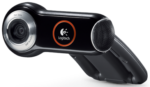 We started with a pair of USB Logitech Webcam Pro 9000 HD, coupled with an open source motion detection package – https://motion-project.github.io.
The following three commands helped:
uvcdynctrl -l lists available camera devices
uvcdynctrl -d /dev/video2 -c shows what parameters (e.g. brightness) are available.
v4l2-ctl -d /dev/video2 --list-formats-ext shows what resolution/frame rates your camera can support.
A motion log level of 7 (INF) gives good general feedback, but for some issues we had to use level 8 (DBG).
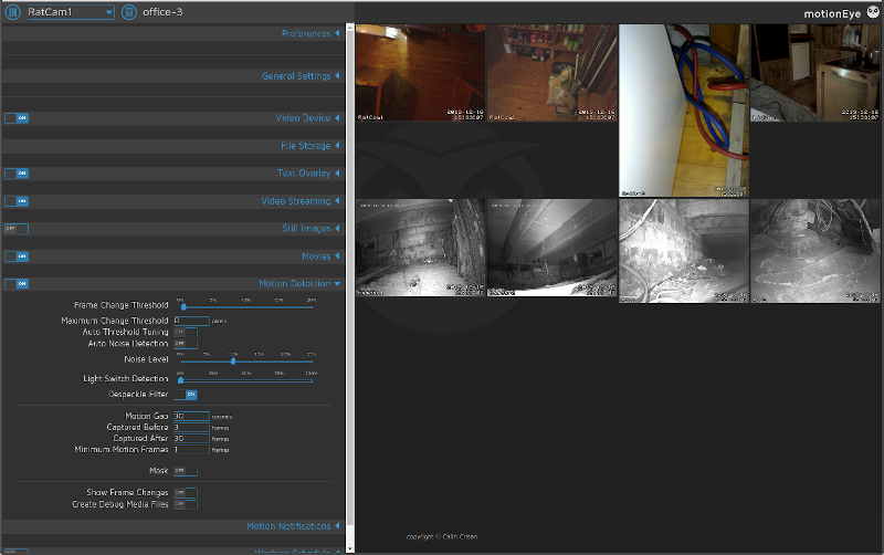
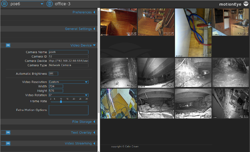
Instead of configuring motion via its text files, there is a nice web-based graphical interface: motioneye
We had to experiment a fair bit with frame rates, resolutions and tuning motion thresholds, but we settled on
FrameChangeThreshold: 0.5%
Noise Level: 10%
MotionGap: 30
CapturedBefore: 3
CapturedAfter: 20
MinimumMotionFrames: 1
 We then added a Logitech C270 webcam
and the built-in camera in an Acer TravelMate 8371 notebook (which was already monitoring the 3 attached USB webcams).
Going Underground

Footage from the four cameras caught the culprit, but to identify the method of entry we needed to film under the floorboards. This meant either lighting up the underfloor area, or utilising night vision cameras. We chose the latter.
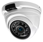
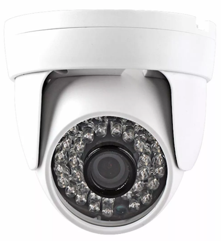
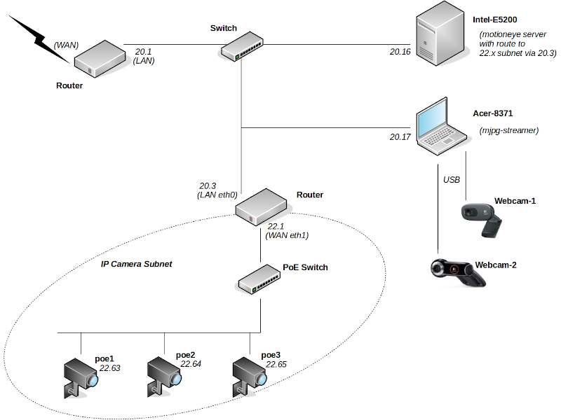
We bought two Besder IP IR webcams (which support the rtsp streaming protocol) and hung them off cat5 cables.
They are not PoE though, so we had to add 12v power wires.
Given the propensity for connecting to cloud servers situated outside the UK, we put the Besders on a separate IP subnet, isolated by a router so they cannot initiate communication. We also gave them no default gateway.
To set up the cameras, we used ONVIF Device Manager running on a Windows 7 virtual machine.
Both cameras were set at 1024×768 @ 10fps
Scaling Up
As we added cameras, the load got too much for the humble CPU in the Acer TravelMate, resulting in dropped frames and in some instances complete failure to record a triggered event. So we moved the motion processing to a separate Ubuntu 18.04 machine. This meant that the Acer only needed to stream the USB webcams, so we replaced motion on the Acer with mjpg-streamer.
(Tip: before trying to stream, first check USB cameras locally with guvcview.)
mjpg_streamer -i "input_uvc.so -d /dev/v4l/by-id/usb-046d_0809_B600F2B8-video-index0 -r 960x720 -f 10 -timeout 15" -o "output_http.so -p 8092" &
Warning: use the /dev/v4l/by-id/usb… device name format – if you use the /dev/video1 style you might find cameras changing id when unplugged and reconnected.
View the resultant stream with mplayer :
mplayer -demuxer lavf http://192.168.20.17:8092/?action=stream
Using mjpg_streamer, even a 2012 Raspberry Pi 1 Model B can stream OK.
Even More Cameras
 Our quest needed more night vision cameras, so we bought another two, this time with PoE to simplify our cabling. ONVIF manager identified these new 2MP/1080P cameras as INGENIC-V01. Fortunately they have an English option on their built-in web interface, so configuring was easier (although the interface is pretty buggy and not identical on the two cameras).
Again we put these IP cameras on a separate subnet. The streaming address for these was:
rtsp://192.168.22.63:554/stream1
(Tip: ffprobe -hide_banner "rtsp://192.168.22.63:554/stream1" quickly gives relevant stream info, for example:
Stream #0:0: Video: h264 (Main), yuvj420p(pc, bt709, progressive), 1920×1080, 25 fps, 25 tbr, 90k tbn, 180k tbc )
So now we had a total of eight cameras, all at 10fps:
4 @ 640×480
2 @ 1280×720
2 @ 720×576 (D1)
A Pentium Dual-Core E5200 @ 2.50GHz monitors all 8 video feeds with motion detection at about 35% CPU. Obviously the load goes up when motion capture is triggered, particularly since streaming to any viewers goes from 1 to 10 fps.
False Positives
So we had 4 standard webcams above ground and 4 InfraRed IP cams under the floorboards. But it soon became apparent that we needed to be able to disable the motion detection of the above ground cams when a person entered the room (to reduce false positives).
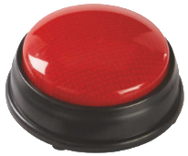
A button to turn off/on motion detection seemed the simplest solution.
We modified a nice big one that came with a game, adding LEDs and a hacked USB interface.
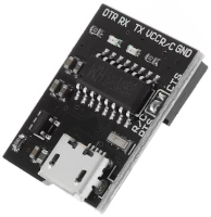
To connect to USB we used CH340G – a USB To Serial 5V 3.3V Break-out USB-TTY. A solder pad must be used to set either 3.3v or 5v. If you don’t do this, the device will probably refuse to be identified by the computer.
When plugged in to a Ubuntu 18.04 machine, dmesg should show something like ch341-uart converter now attached to ttyUSB0, whilst lsusb shows QinHeng Electronics HL-340 USB-Serial adapter.
The R/C pin is either RequestToSend or ClearToSend, again controlled by a solder pad. We set it to CTS.
As a simple test, if you jumper TX → RX and run sudo screen /dev/ttyUSB0 115200 anything typed should be echoed back in the screen session. (Ctl-A ? shows screen options, Ctl-A D will exit.)
statserial can be used to monitor the interface – sudo statserial /dev/ttyUSB0 (very useful when debugging)
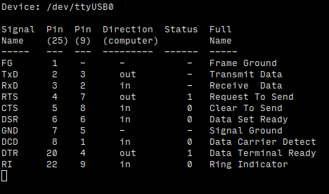 Grounding the CTS (R/C) pin raises CTS.
We connected the LEDs in the button to the DTR pin. So we just needed a simple loop to Monitor CTS:
CTS == 1)
set DTR=1 (to light LED)
enable motion detection - lwp-request http://localhost:7999/0/detection/start
CTS == 0)
set DTR=0 (turn off LED)
disable motion detection - lwp-request http://localhost:7999/0/detection/pause
(The 0 in the lwp_request command means all cameras – individual cameras can also be specified, but be aware that the number corresponds to the camera’s position in the motion.conf file, not the Camera ID as shown under the Video Device section of the motioneye settings panel (which is derived from the numeric suffix in the camera config filename, e.g. camera-21.conf will have Camera ID 21.)
This was implemented with a bit of shellscript and some simple C code:
monitor_cts is a C program continually running in the background against /dev/ttyUSB0. It uses ioctl(fd, TIOCMIWAIT, TIOCM_CTS) to identify change of state of the CTS pin, and create/delete a temporary file /tmp/button_pressed.
mc.sh is a shell script running a 1 second loop.
If it sees the /tmp/button_pressed when motion detection is on, it pauses motion detection (via lwp-request "http://localhost:7999/2/detection/pause) and calls a C program set_DTR.c (which uses ioctl(fd, TIOCMSET, &flags)) to turn off the light. A timer is also started.
If it sees the /tmp/button_pressed when motion detection is paused, it restarts motion detection (via lwp-request "http://localhost:7999/2/detection/start) and calls set_DTR.c to turn on the light.
If the timer runs out (e.g. after 30 minutes) and the button has not been pressed again, we assume someone forgot to press the button so we restart motion detection.
Well?
At time of writing (December) we haven’t fully banished the visitor, although appearances have become less regular. However we’ve learnt a fair bit about CCTV…
Observations
- The images from our USB Webcams show ‘sparklies’, even in a well-lit scene, whereas the image quality from the IP Cameras is very good.
- The IP cameras vary in features and the ability to configure them via an English interface without having to utilise external cloud based services. Although there are lots of pictures of items on banggood.com, descriptions can be inaccurate and backup technical information rather sparse.
- Whilst the button disable/enable motion detection idea is helpful, a simple PIR at waste height to detect people entering the room would be less prone to people forgetting to press the button (particularly when their hands are full).
- Cameras are never in the right place, and you always seem to need more.
- WiFi cameras might seem to make things easier, avoiding the need for a network cable. But they still have to be powered and changing a battery in a camera under the floor is not so convenient.
- Rats are less likely to show when the temperature is near freezing.
And Yet More Cameras
We added another four IP cameras, again sourced from banggood.com. But we had trouble setting the correct static IP addresses.
Some cameras start with a default IP address (e.g. 192.168.1.10), whilst others have DHCP enabled. But sometimes they just grab a random address on the current subnet (not a link-local 169.254.x.x APIPA address, nor an address from the DHCP pool), which could of course clash with the address of an existing device.
Also, some cameras will not respond to ONVIF Device Manager – so we switched to using CMS client software (2012) from hiseeu.com on a WinXP virtual machine. This communicates with the cameras over port 34567/tcp. This proved more successful and were able to more effectively configure the new (and our existing) cameras. We set the new cameras to a resolution of 704×576 .
So our camera total is now 12 – three USB, eight IP and a built-in-to-notebook-lid.
For the underfloor cameras, we found the following motioneye settings gave the best motion detection, with minimal false-positives:
VideoDevice/FrameRate: 10
VideoStreaming
- StreamingFrameRate: 10
- MotionOptimization: on
StillImages: off
Movies: on
MotionDetection
- AutoThresholdTuning: on
- AutoNoiseDetection: on
- LightSwitchDetection: 0
- DespeckleFilter: on
- MotionGap: 30
- CapturedBefore: 10
- CapturedAfter: 15
- MinimumMotionFrames: 1
MotionNotifications/SendAnEmail: on
Investigating the Cameras
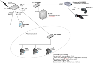
With even more cameras on order, we decided to improve the segregation of our network so that we could more easily monitor what the cameras are up to.
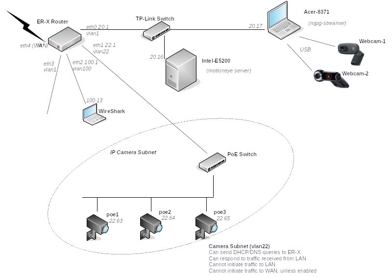
Instead of using the second router to isolate the cameras, we configured the main router (a Ubiquiti ER-X) with a separate VLAN on the port to which the cameras are connected. Then we defined firewall rules to prevent the cameras initiating traffic within our LAN (i.e. they can only respond to requests from our motioneye server), with an additional option of allowing them direct access to the Internet if we choose to. We found this tutorial is very helpful in configuring the ER-X switch interfaces. Note that unlike our previous network setup, where we utilised a second router intentionally “the wrong way round” so that NAT kept things apart, we now have to configure each IP camera with a default route of x.x.22.1.
Having connected a laptop running WireShark traffic monitor to port eth2 on the ER-X, we ran the following CLI commands on the ER-X to mirror the camera traffic on eth1 to our monitoring laptop on eth2:
sudo /sbin/switch mirror monitor 2 # set eth2 as monitoring port
sudo /sbin/switch mirror target 1 3 # mirror traffic from port eth1 to monitoring port
When we ran WireShark on laptop 100.13 (mirroring vlan22 camera traffic), captured traffic for just a minute, then applied a display filter to ignore traffic to the motioneye server and monitoring laptop of
not ip.addr==x.x.20.16 and not ip.addr==x.x.100.13
and viewed Statistics/Conversations:IP4 we saw interesting attempts (unsuccessfully, of course, due to our firewall ruleset) from some of the cameras to reach out to the following IPv4 addresses:
- 8.8.4.4 (Google DNS)
- 8.8.8.8 (Google DNS)
- 18.184.211.224 (xmeye – Amazon)
- 51.137.137.111 ((time.windows.com NTP server)
- 54.93.73.119 (Amazon)
- 58.96.174.209 (Hong Kong)
- 112.74.15.239 (Hangzhou)
- 114.114.114.114 (DNS in Nanjing)
- 118.190.21.209 (Hangzhou NTP server)
- 119.29.29.29 (Shenzhen)
- 120.25.129.41 (Hangzhou)
- 162.159.200.123 (Cloudflare NTP server)
- 180.76.76.76 (DNS in Beijing)
- 198.11.172.169 (Alibaba)
- 202.96.128.86 (DNS in Guangdong)
- 223.5.5.5 (Ali DNS, looking for logsvr.xmcsrv.net)
Where we were able to access the configuration settings of the cameras (either via ONVIF Device Manager, CMS client software or native web interface), we tried to disable unnecessary outgoing traffic – email alerts, cloud syncing etc. However not all settings could be changed, so we could not eliminate all outgoing traffic attempts (although the firewall ultimately blocks them).
We tried replacing mjpg-streamer with gstreamer on the Acer laptop streaming the webcams, the intention being to send H.264 instead of MJPEG streams to motioneye. However, whilst this did decrease the network bandwidth used between the laptop and the motioneye server, the CPU required on the laptop was substantial – 60% of CPU for just one camera stream. Unfortunately hardware accelerated H.264 encoding is only available on newer Intel CPUs with integrated graphics, and recent Nvidia video cards.
February 2021
We moved motioneye to a more powerful host – an Intel I5-2400 based machine – meaning less likelihood of dropped frames due to 100% CPU utilisation during periods of activity.
We have replaced the laptop used to stream the USB webcams with a 2GB Raspberry Pi 4B (with a Power over Ethernet HAT, reducing the cable count). This has allowed us to utilise gstreamer to send H.264 to motioneye.
From the Logitech Webcam Pro 9000:
gst-rtsp-server-1.14.4/examples/test-launch -p 8091 "( v4l2src device=/dev/v4l/by-id/usb-046d_0809_A8BFE2B8-video-index0 ! queue ! video/x-raw,format=YUY2,width=640,height=480,framerate=15/1 ! videoconvert ! omxh264enc target-bitrate=500000 control-rate=1 ! video/x-h264,profile=baseline ! rtph264pay config-interval=1 name=pay0 pt=96 )"
From the Logitech C270:
gst-rtsp-server-1.14.4/examples/test-launch -p 8093 "( v4l2src device=/dev/v4l/by-id/usb-046d_0825_A00DA2E0-video-index0 ! queue ! image/jpeg,format=MJPG,width=640,height=480,framerate=15/1 ! jpegdec ! omxh264enc target-bitrate=500000 control-rate=1 ! video/x-h264,profile=baseline ! rtph264pay config-interval=1 name=pay0 pt=96 )"
Note that whilst both cameras are capable of streaming 640×480 YUYV (YUY2) @15fps (which puts 10MBit/s over USB), a V4l2 driver bug meant that we had to use 640×480 MJPEG @15fps instead for the C270 (which puts 5MBit/s over USB). This does incur a higher CPU cost on the Pi to decode the MPJEG, but since the Pi is utilising hardware H264 encoding, the three USB camera streams are using a combined total of less than 20% of a single CPU core of the quad-core Raspberry Pi, and sending no more than 1Mbits per second of video traffic to our motioneye server.
Indoor light levels do present a problem for tuning the motion detection of the webcam streams. Start by minimising “shimmering/sparklies” in the image, by tweaking the USB camera output captured on the RTSP server (the Raspberry Pi in our case) to ensure the gain is not too high:
v4l2-ctl --device=$DVC --set-ctrl=brightness=160 # 0-255
v4l2-ctl --device=$DVC --set-ctrl=gain=160 # 0-255
v4l2-ctl --device=$DVC --set-ctrl=power_line_frequency=1 # 50Hz
v4l2-ctl --device=$DVC --set-ctrl=exposure_auto=1 # 1=manual, 3=auto
v4l2-ctl --device=$DVC --set-ctrl=exposure_absolute=55 # 1-10000
v4l2-ctl -d $DVC --list-ctrls-menus will give the ranges for each video device.
Then play with the motioneye detection values. Instead of adjusting the percentage sliders in the Web interface, you can achieve more granular control over the Frame Change Threshold and Noise Level values by directly editing the camera-xx.conf files in /etc/motioneye, then restarting motioneye with systemctl restart motioneye.
Suggested procedure for motion tuning – set the following, then initially adjust the threshold value. Once a happy medium is achieved, set locate_motion_mode and text_changes to off.
locate_motion_mode on
locate_motion_style redbox # Draw a box around the area identified as motion.
text_changes on # Show number of changed pixels in the area (displayed in top right).
pre_capture 0 # Buffer no frames before motion is triggered (otherwise can cause dropped frames).
post_capture 50 # Capture 50 frames after motion detect stops. At 15fps this is ~3.5 seconds.
event_gap 10 # If motion stops and restarts within 10 seconds, consider it one event, and therefore one video recording.
lightswitch_percent 10 # If greater than 10% of all pixels change in one frame, assume due to lighting change and do not trigger motion.
#noise_level 10 # Level of intensity change of a pixel for it to count as “changed”. Higher values consider more changes as just “noise”.
noise_tune on # Auto set the noise level – i.e. ignore manually set noise_level value.
despeckle EedDl # Remove more noise, and consider connected pixels which have registered change as a labelled area. This is an important setting.
threshold 150 # Labelled area of connected pixels which have registered change must contain at least 150 pixels to trigger a motion event. The lower this value, the more sensitive the motion detection, but the greater likelihood of false detections.
Tip: When you are monitoring the camera outputs via a browser pointed at motioneyehost:8765, to reduce network traffic from motioneye to your browser set Preferences:Frame Rate Dimmer to 5%. This does not affect motion detection or camera recording quality.
The motioneye web interface orders the camera feeds by camera id, which is a suffix in the camera config filenames. To change the order, rename the camera-nn.conf files in /etc/motioneye/. Note that the id is also held in the comment block at the top of each .conf file, so you should also update the # @id n line in each config file so that it corresponds to its filename. Also update /etc/motioneye/motion.conf to reflect any changes you’ve made. All being well, any archived videos or pictures in /var/lib/motioneye/ should remain attached to the appropriate camera (due to the target_dir parameter in each config file still pointing to the old camera directory name – although this could confuse you in the future!) If you are also using the lwp_request command to control motion detection on specific cameras, you’ll also need to update the camera-ids in your URLs.
Then run systemctl restart motioneye.
To monitor the CPU and network load on the Raspberry Pi and the motioneye server we used htop, iftop and usbtop.


